3. Connect a cable on the midpoint COMMON (36) of the ter‐
minal block.
4. Connect the second cable on the WORK (35) of the terminal
block or on the REST (37) depending on the function to be
performed.
4.9 4…20 mA outputs (AO1 to AO2)
4…20 mA outputs are used to transfer data to a PLC or to control a
dosing pump via a 4…20 mA signal. The analog outputs are gener‐
ative and operate with an internal voltage of 12 VDC. The max‐
imum load is 500 Ω.
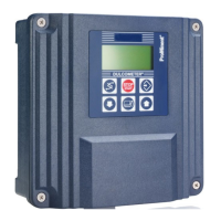
Fig. 20: A01
1. Remove the protective sheath and strip wires on 7 mm.
2. Pass the cable through a cable gland.
3. Connect the two wires of the 4…20mA loop to + (12) and –
(13).
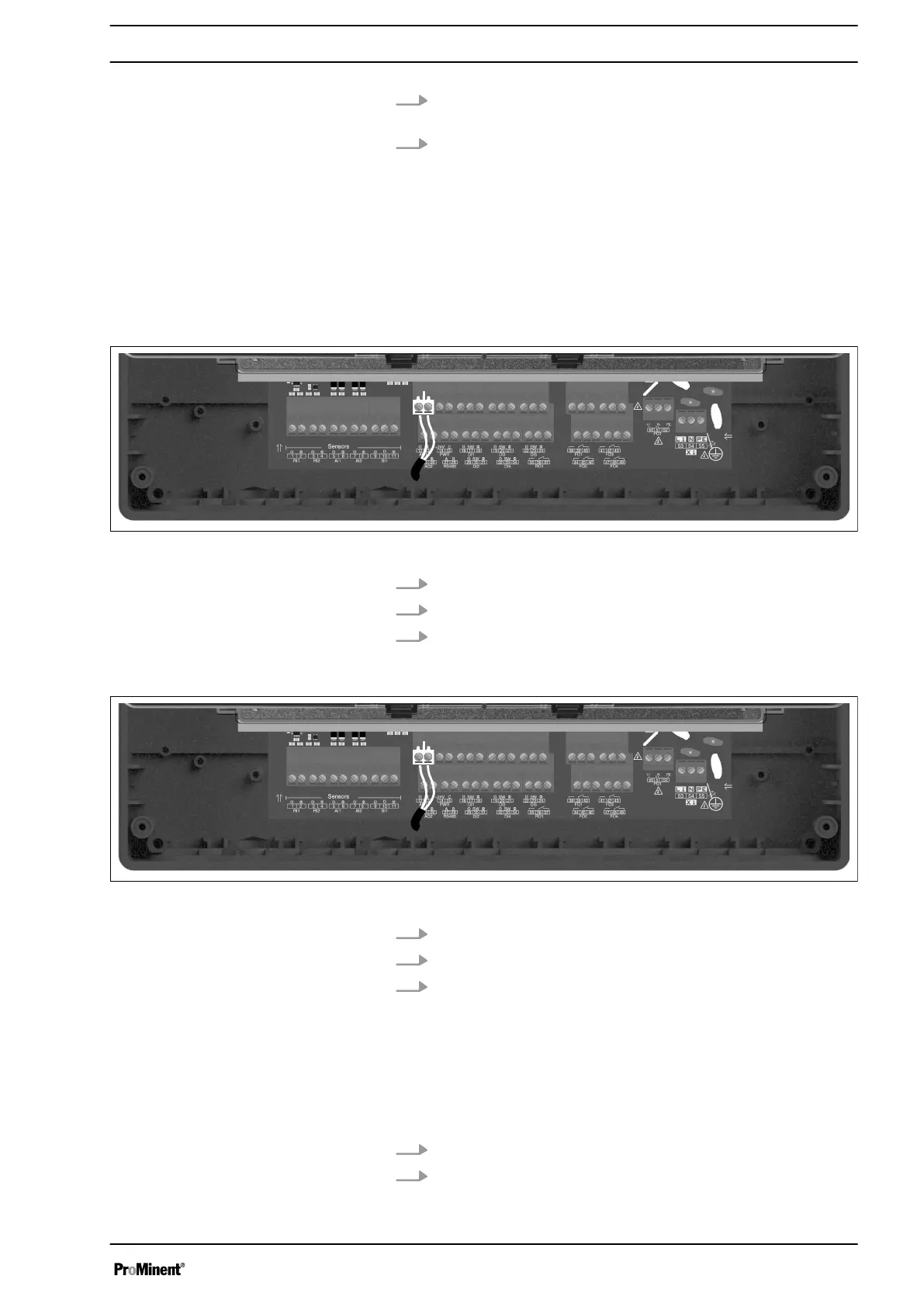
Fig. 21: A02
1. Remove the protective sheath and strip wires on 7 mm.
2. Pass the cable through a cable gland.
3. Connect the two wires of the 4…20mA loop to + (25) and –
(26).
4.10 Power supply output (PWR)
If necessary, chlorine or bromine sensors may be used that require
external power.
1. Connect the strand + of the alimentation on +24V (17)
2. Connect the strand - of the alimentation on C (18).
Assembly and Installation
25