Operation and Maintenance Manual Rev M(ii) 4/03
- 21 -
o Slowly increase the material pressure regulator until material flows from the disconnected material line.
o Turn the outlet material valve to the closed position.
o Bleed pressure for pressure vessel and adjust the material pressure regulator to 0 P.S.I
o Reconnect the material line to the inlet port of the flow monitor.
o Open the valve (dispense or spray) using the manual purge procedure outlined in the operations and
maintenance manual.
o Turn the material outlet valve to the open position.
o Slowly increase the material pressure to the target operating pressure.
o Continue the manual purge procedure for each valve until the material flows free of air.
Determining the Correct Material Volume
Before attempting to determine the appropriate material volume, the operator should have a completed path
program, since any changes to a program alters the flow data results. With the completed program loaded
into memory, the operator should enter the Manual mode, position the board correctly with respect to the
board stops and run a singular cycle. For more information on the Manual mode, please consult page 21 of
the Operation and Maintenance Manual.
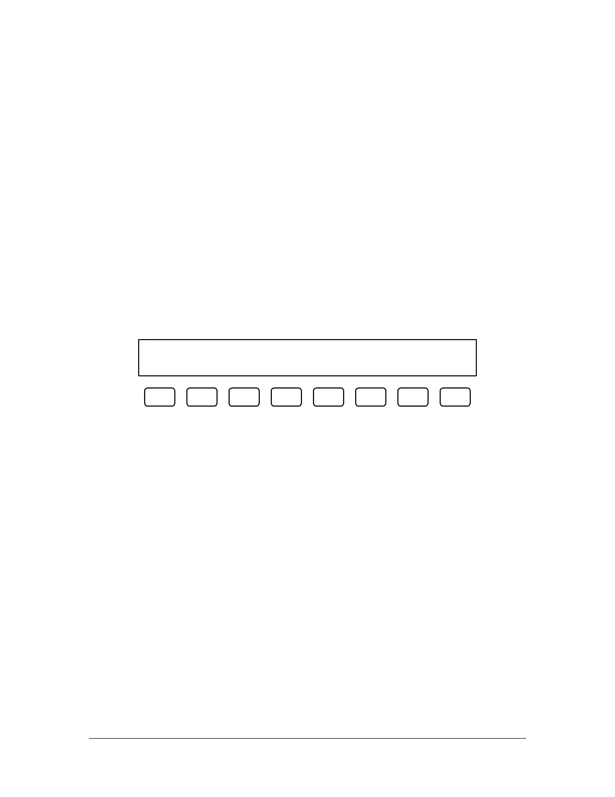
After the singular cycle finishes, it displays the following screen:
Flow Data Set Pt.=00.00cc Dv.=00.0%
Mat.=00.00cc. Press F1 to continue.
F1 F2 F3 F4 F5 F6 F7 F8
The ‘Mat’ value is the amount of material dispensed. The operator should go to the Flow Control mode and
change the flow set point to the ‘Mat’ value that appeared on the flow data screen, then return to the
singular cycle option to run more cycles and verify the consistency of the path program.
NOTE: The above screen does not display if the material target level is set to zero in the Flow Control
mode. See the section Flow Control Mode for information on changing the material target level.
Setting the Material Volume Check
There are two methods of setting the material volume check parameters.
1) Go to the Flow Control mode and adjust the material volume and deviation parameters.
2) Program the settings into the path program. Two variables are used: AC_SET and AC_DEV.
AC_SET is the setpoint for the material flow, which can range from 0 to 99. AC_DEV is the percent
deviation allowed, which can be anywhere from 0 to 99. As an example, entering the following line
into a path program: AC_SET=0.500;AC_DEV=5 would put the volume setting at 0.5 cc and the
allowable deviation at 5%.
If the settings are programmed into the path program, they are used instead of the settings from Flow
Control mode. If no settings are programmed in the path, the machine defaults to the Flow Control mode
settings.
Auto Cycle Flow Error
The Auto Cycle checks the material flow after every cycle if the error is turned ON in the Flow Control
mode. If the volume was within parameters, no indication is given to the operator. In cases where the