PART REPLACEMENT Replacing a width transmitter board
Cubiscan 325 Service Manual 29
connectors outwards. These ribbon connectors are
indicated in Figure 21.
5. Disconnect the two power cables, indicated in
Figure 22.
6. Unscrew the six screws holding the board in place,
using the small Phillips screwdriver.
7. Carefully remove the damaged board and replace it
with the new receiver board. Handle the board with
care; the LED’s are fragile and can be broken. Make
sure you orient the board correctly, with the power
connectors in the bottom-left corner.
8. Screw the replacement board into place.
9. Reattach the power cables and receive ribbons, as
indicated in Figure 21 and Figure 22. Make sure the
ribbon cables have been firmly locked into place,
with both tabs securely snapped.
10. Replace the gate cover and screw it into place.
11. Power the Cubiscan 325 on.
12. You now need to run a threshold test. Go to Menu >
Diagnose > Gate. Move the gate to the middle of
the Cubiscan and then tap ALL. This test will take
several minutes to complete.
13. Your Cubiscan should now be functioning normally.
Replacing a width
transmitter board
This section describes how to replace a width
transmitter board.
Items needed
–Regular and small Phillips screwdriver
–3/16'' nut driver
–Replacement width transmitter board
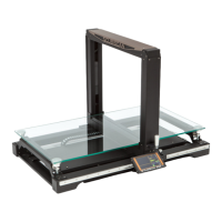
Figure 22
Height transmitter inside bottom view
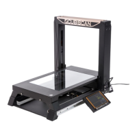
Figure 23
Width transmitter gate cover
Figure 24
Front gate cover