23
©2006 Sunrise Medical
POWER BASE SECTION
Motors
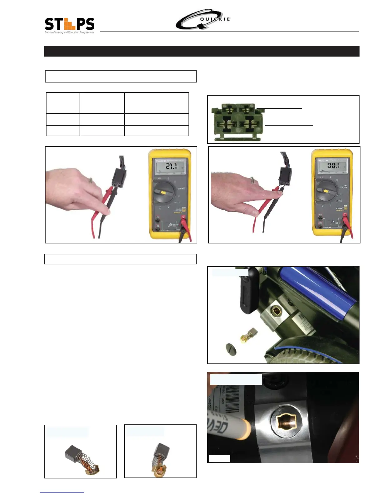
Brake Solenoid
Motor
Motor Connector
Fig 1.19
Fig 1.20
Motor Motor
Resistance
Brake Solenoid
Resistance
Standard 0-2 ohms 21.0-22.0 ohms
Encoder 0-2 ohms 15.0-17.0 ohms
Checking the Motor Brushes
Brush Assembly
Wire between Coil
Top Solder
Commutator Inspection
Fig 1.21
Fig 1.22
Fig 1.23
Fig 1.24
Note: When removing brushes from the motor for
inspection, please note orientation and location of the
brushes as they are removed from the motor (fi g 1.21).
The brushes are “burned in” to the commutator and
reinstallation in a location or orientation not matching
the pre-inspection location may negatively affect motor
operation.
Checks:
• How smooth is the brush surface – did it create “C”
shaped groove?
• If there is less than 1/4” brush material left the
Brushes should be replaced.
• How the wire between the coil looks – did it discolor
(fi g 1.22)
• Did the Top soldered joint melt (fi g 1.23).
• How does the commutator look after the brush has
been contacting the surface (fi g 1.24).
Checking Motor Resistance and Continuity
Fig 1.18