36©2006 Sunrise Medical
POWER BASE SECTION
Anti-pitch Damper Mechanism Cleaning
If the Anti-Pitch Mechanism becomes contaminated
with grease or oil it will be necessary to remove and
disassemble it for cleaning.
Raise the chassis of the chair on a stable •
platform, such as jack stands, so that all wheels
are off of the working surface.
Disconnect the motor power lead from the •
controller and remove the motor wiring through
the chassis so that the motor assembly can be
removed from the chair chassis.
Remove the side shroud and set aside. (Refer •
to Shrouds section for removal instructions)
With the motor cog release engaged, loosen •
and remove the drive wheel securing lug nuts
and the drive wheel. (Refer to Drive Wheels
section for instructions)
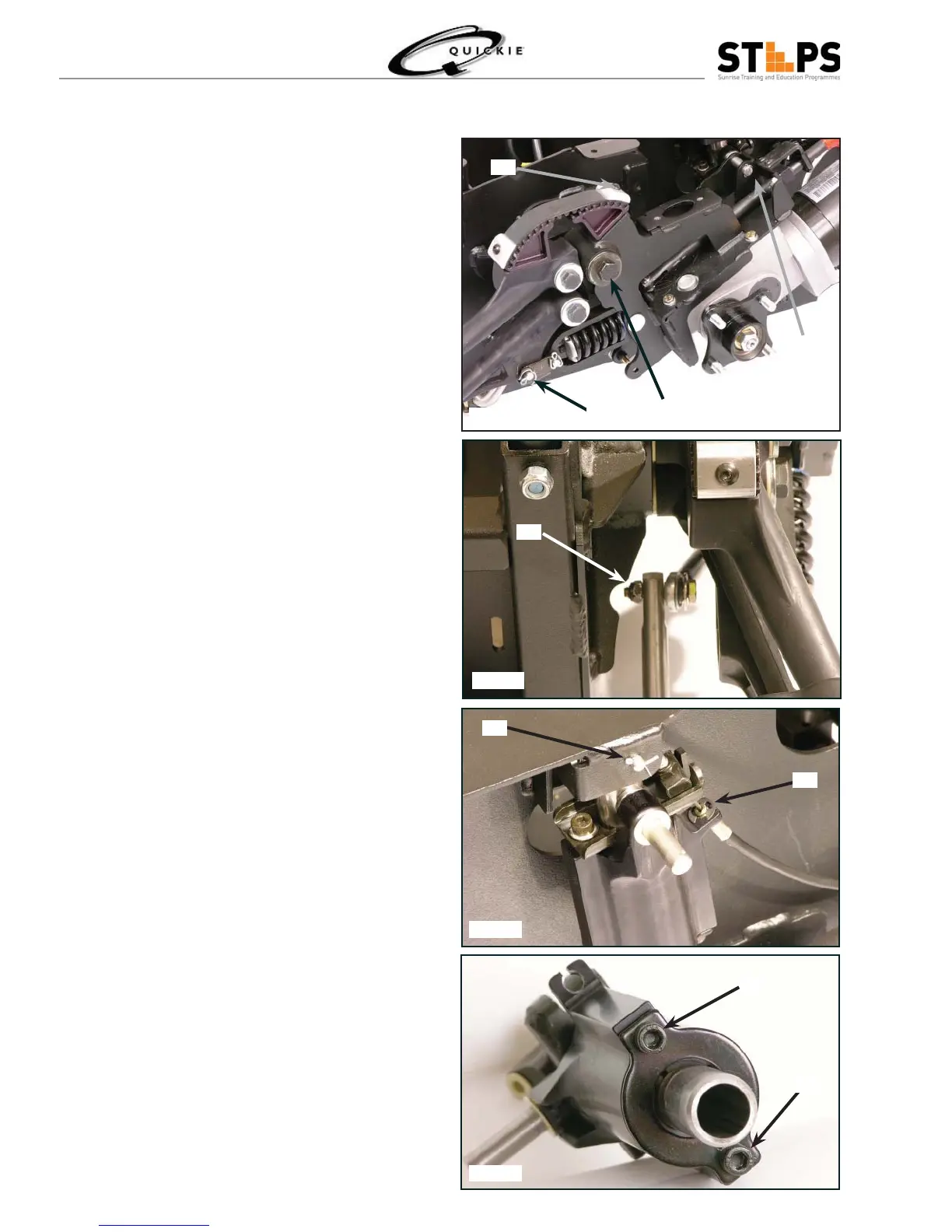
Remove the front most cotter pin (A) on the •
suspension linkage.
Remove the small cotter (B) pin on the Anti-•
Pitch Damper post.
Remove the main motor assembly bolt (C).•
Remove the button head cap screw (D) that •
holds the belt clamp and belt to the motor mount
pulley.
Use a 10 mm wrench to remove the M6 bolt •
(E) attaching the Anti Sway bar to the Motor
assembly.
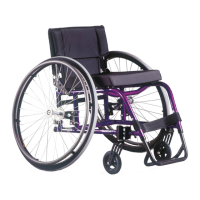
Pull the motor assembly away from the chassis •
using a rocking motion.
Remove the 1/6 x 1/2 cotter pin (F) and the •
Anti-Pitch Damper Rod Pivot Pin that secure
the Anti-Pitch assembly to the chassis.
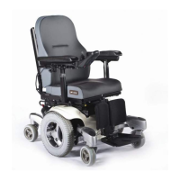
Remove the E-clip (G) that holds the cable to •
the Anti-Pitch assembly
Remove the two socket head cap screws (H)on •
the bottom of the Anti-Pitch assembly
During reasembly the two socket head cap •
screws (H) should be torqued to 7-9 foot-
pounds or 10-12 newton-meters. The M6 bolts
(E) that attach the Anti sway bar to the Motor
assembly should be torqued to 6 ft-lbs or 8.13
Newton Meters. The Main Motor Bolt (C) should
be torqued to 55-60 Newton Meters (40-.60 ft-
lbs)
A
B
C
D
E
F
G
H
H
Fig 1.64
Fig 1.65
Fig 1.66
Fig 1.67