28©2006 Sunrise Medical
POWER BASE SECTION
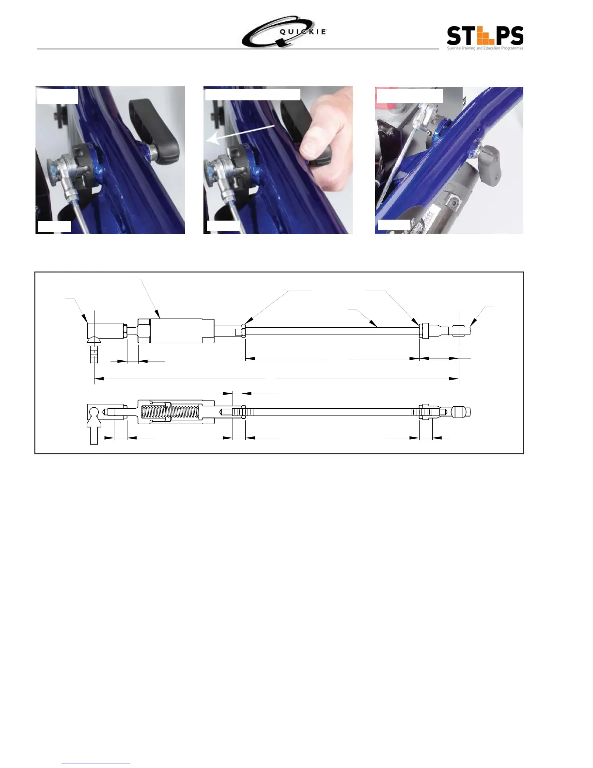
Groove Free Wheel Assembly
Engaged
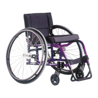
Push in - Rotate down
Free Wheeling
Fig 1.40
Fig 1.41
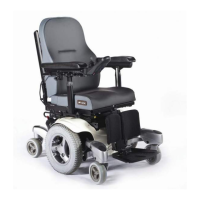
Fig 1.42
12”
1 1/4”
3/8”
5 3/4”
ROD FASTENING NUT
COMPENSATOR ASSEMBLY
ROD END
BALL JOINT
COG RELEASE ROD
7/16”
7/16” 7/16”
8
THREAD ENGAGEMENT
Pre-Assembly:
Thread Rod Fastening Nut and Rod End to the Cog Release Rod – turn about 7 Full turns.1.
Tighten Rod Fastening Nut snugly.2.
Do the same for other end of rod, thread nut and Compensator Assembly. Do not over-tighten at this time.3.
Set the distance between the fastening nuts to be approximately 5 ¾ inch (5.7 inch).4.
Add Ball Joint assembly to Compensator and thread another fastening nut but keep it loose at this time5.
Set the distance to be approximately 3/8 inch (.35 in) between fastening nut and Compensator.6.
Final Assembly:
The Motor Should be Set in “DRIVE Mode” position before installing the COG.1.
Make sure that the Cog Release Rod Handle is Parallel with the Chassis Tube Pointing towards casters.2.
Fasten the Cog Release Rod assembly to the Motor Lever and Cog Release handle assembly.3.
Add Batteries and any additional parts to system (Ex. Seating System) to add weight for proper adjustment 4.
Note: Further adjustment is available via the Compensator thread if required.
Now adjust the Compensator thread until slop on Cog release Rod side is gone.5.
Dis-engage and try to push wheel for any gear noise, adjust more if necessary.6.
Try a couple more times to ensure “Drive” and “Free Wheel” operation are working properly – fi nish with 7.
tightening all fasteners securely.
Fig 1.43