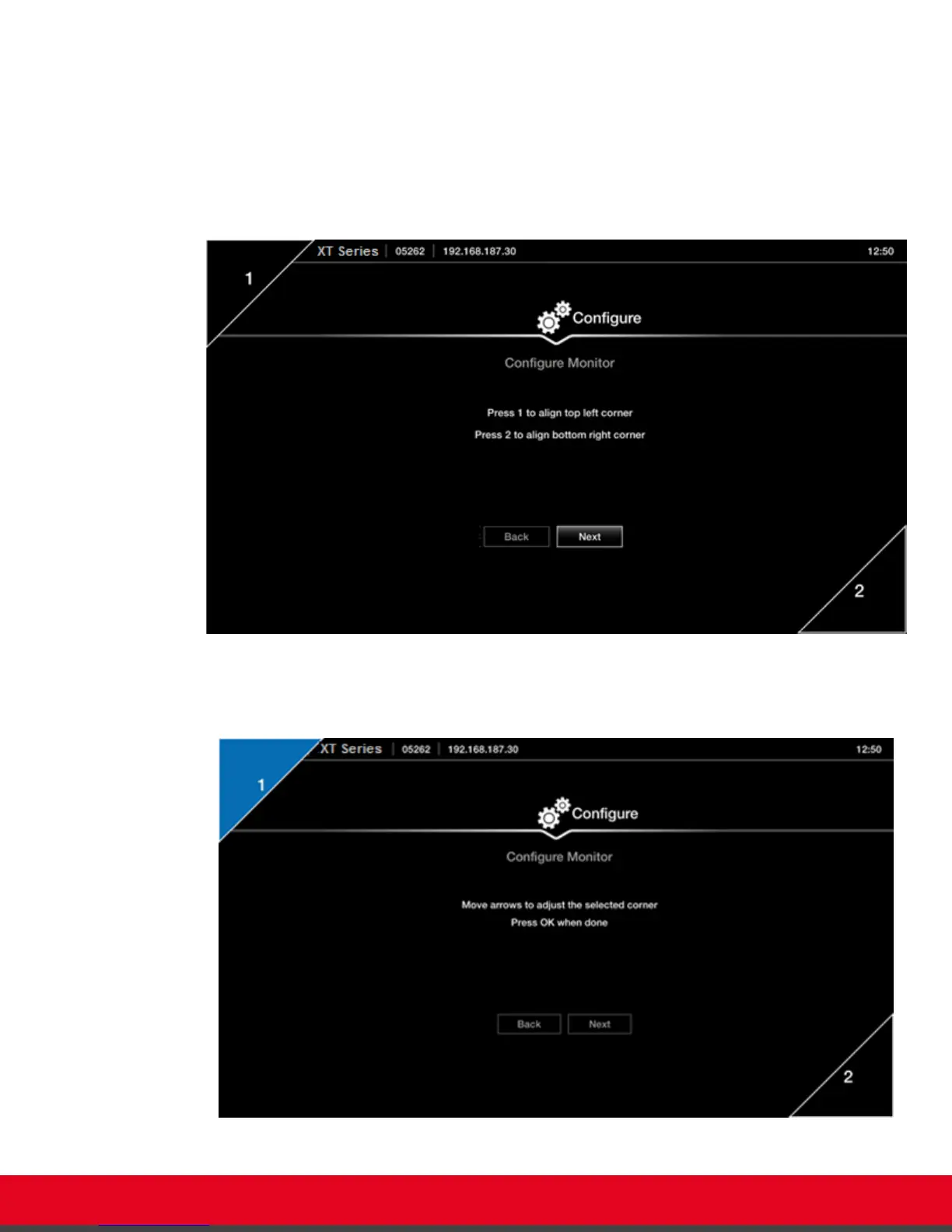
Procedure
1. Examine the image on the monitor to decide if you need to adjust the image position.
The triangles in the top left corner and bottom right corner must be fully visible so that the
white border of the triangle is fully visible on all sides.
If the image is centered correctly, skip this procedure and select Next.
Figure 15: Examining the image position
2. Press 1 to align the top left corner.
Figure 16: Adjusting the image position
User Guide for Scopia XT5000 Series Version 3.2 Getting Started | 26
 Loading...