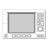
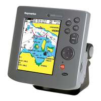
5-12 Raychart 425 Chartplotter
suitable connector block to connect to the extension cable. The supplied
power cable cores have a cross-section of 2.0mm
2
(15 AWG).
Longer power cable runs may require larger wire gauges to minimize any
voltage drop in the cable. In order to determine the correct supply cable
size if the power cable must be extended, estimate the length of cable
between the vessel’s main power source and the connector block, then
select the wire size determined by the distance as indicated in Table 5-2 .
The DC power and NMEA inputs/outputs should be connected to the
POWER/NMEA cable at the rear of the chartplotter. The cable colors are
detailed Table 5-3 .
➤ Connect to the power supply using the power cable supplied:
1. Connect the moulded connector to the
POWER/NMEA connector on
the rear of the chartplotter. Run the free end back to the vessel’s distri-
bution panel or, if insufficient cable length, to a junction box.
2. Cut the cable to length and connect the red wire, via a 1A quick blow
fuse or circuit breaker, to the +ve battery terminal and the black wire
to 0V (-ve battery terminal).
Table 5-2: Maximum Power Cable Extension Lengths
Power Cable Core mm
2
:
1.5 2.0 2.5 4.0 6.0 10.0
Equivalent AWG: 16 15 14 12 10 8
Maximum Extension (feet): 36 49 65 98 147 230
Maximum Extension (meters): 11.0 15.0 20.0 30.0 45.0 70.0
Table 5-3: Power/NMEA Cable Colors
Function Color
Battery negative Black
Battery positive (10.0VDC to 18.0VDC) Red
NMEA input (+ve) White
NMEA input (-ve) common Green
Not connected Gray
NMEA output (+ve) Yellow
Data output (-ve) common Brown
Not connected Screen
 Loading...