18 | Gilat Satellite Networks | Confidential and Proprietary Information
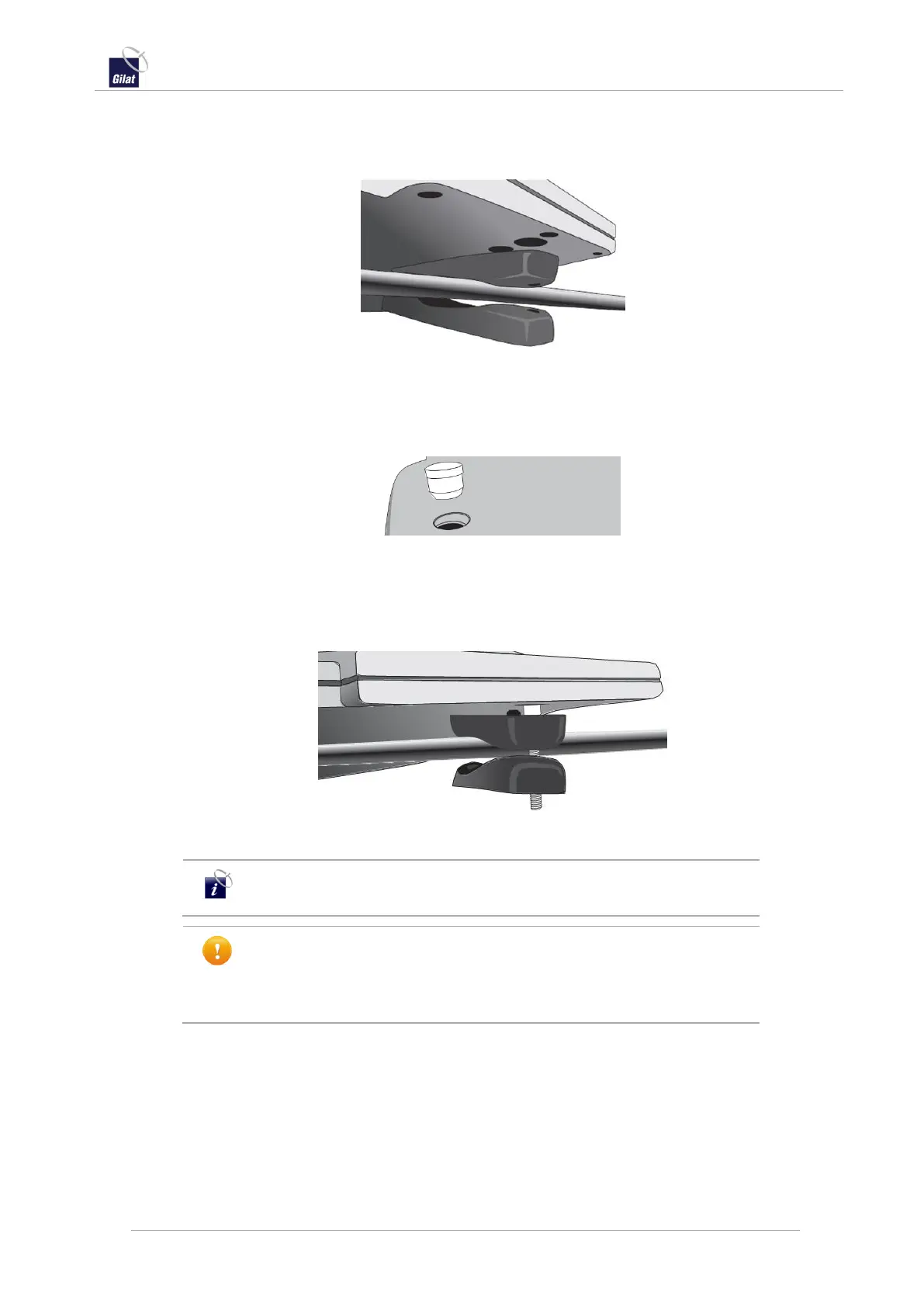
b. Insert the lower bracket with the rubber pad installed under the crossbar
or leg, so that it is in-line with the upper bracket that is resting on the
crossbar.
Figure 16: Lower bracket placed under the crossbar
c. Access the two head screws (No. 9) through the holes on the top of the
antenna and thread them through both the upper and lower bracket
assemblies.
Figure 17: Placement of top cover plug
d. Use an Allen key through the top of the antenna to tighten the screws so
that the upper and lower brackets fit tightly around the crossbars or legs.
Do not over tighten.
Figure 18: Secure clamp with head screw
It is highly recommended to apply a low strength liquid thread lock
to the head screws before inserting into the brackets.
Ensure that the mounting brackets are adequately secured so that
as much of the crossbar’s surface is covered by the upper and lower
clamps as possible. Failure to do so may cause antenna to become
unstable.
3. Once all mounting brackets are in place and secure:
a. Snap the top cover plugs back into the antenna to cover the access for the
head screws.
b. Perform a thorough inspection of all four brackets to ensure the antenna is
secure and stable.
 Loading...