PG-FP5 CHAPTER 5 EXAMPLE OF OPERATION USING PROGRAMMING GUI
R20UT0008EJ0400 Rev. 4.00 Page 118 of 240
Jul 15, 2010
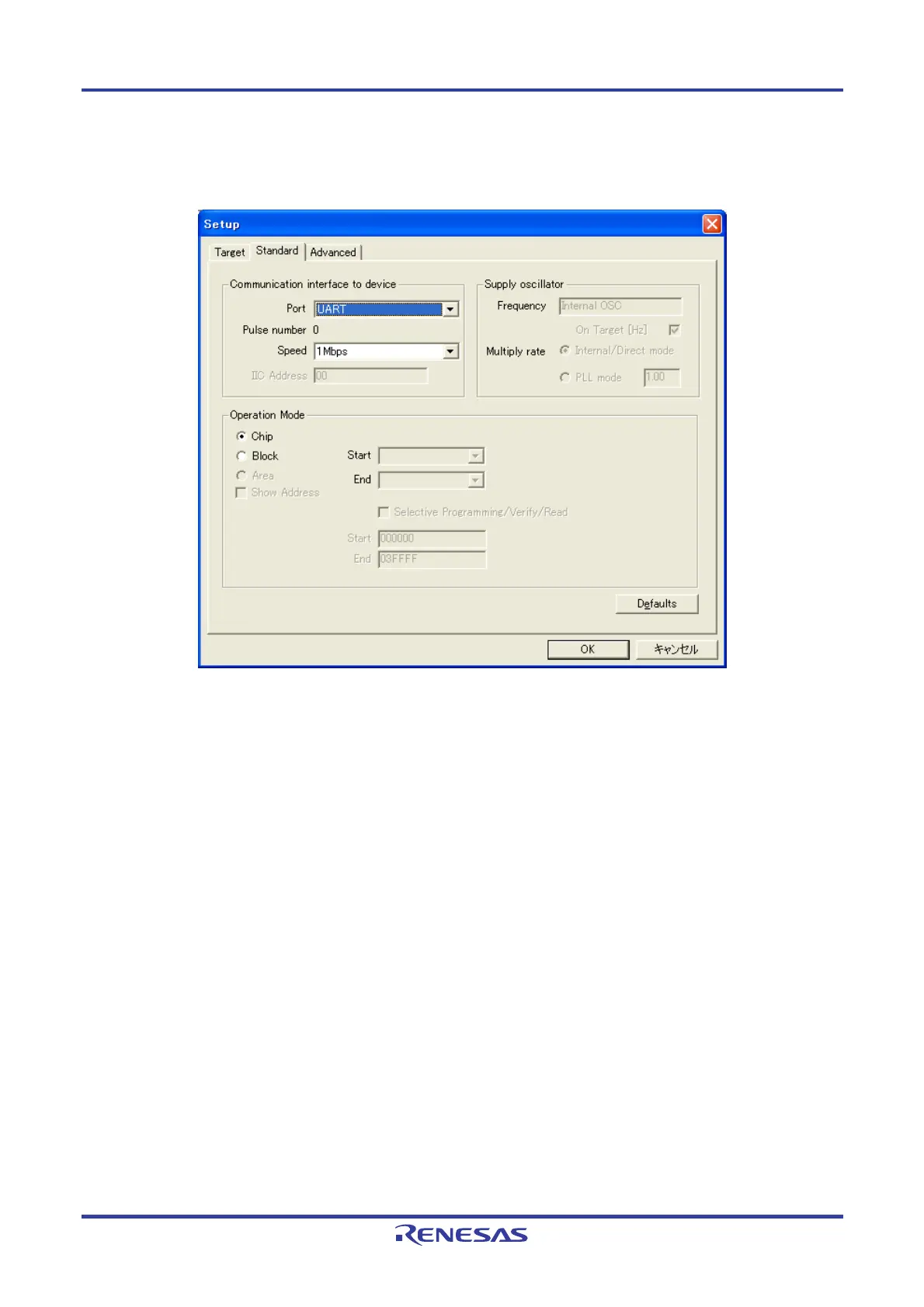
<9> Click the [Standard] tab.
Figure 5-14. Device Setup Dialog Box - [Standard] Tab
<10> Set the items in accordance with the programming environment used. In particular, set the [Communication
interface to device] area and [Supply oscillator] area in accordance with the specifications of the device selected.
Specify a flash memory range to be manipulated in the [Operation Mode] area (the flash memory range that can
be set is defined by the PR5 file according to the specifications of the device).
In this example, it is assumed that the following settings are made.
[Communication Interface to device] area
Port: UART
Speed: 1M Baud
[Supply oscillator] area
On Target: Unavailable (using internal oscillator)
Frequency: Unavailable (Internal OSC)
Multiply rate: Unavailable (Internal/Direct mode)
[Operation Mode] area
Chip

 Loading...


