PG-FP5 CHAPTER 5 EXAMPLE OF OPERATION USING PROGRAMMING GUI
R20UT0008EJ0400 Rev. 4.00 Page 119 of 240
Jul 15, 2010
<11> Click the [Advanced] tab.
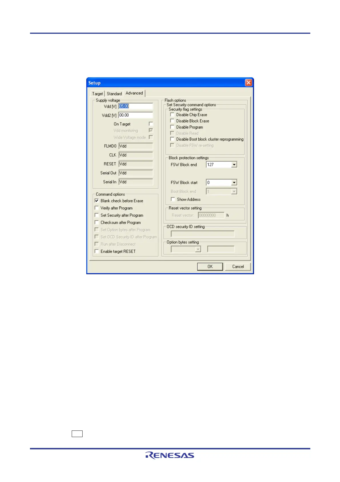
Figure 5-15. Device Setup Dialog Box - [Advanced] Tab
<12> Check the information in the [Supply voltage] area to make sure that they are set in accordance with the
programming environment used.
In this example, it is assumed that the following settings are made.
[Supply voltage] area
Vdd[V]: 5.00 V (Follows the value set in the PR5 file.)
Vdd2[V]: 0.00 V (Not used; follows the value set in the PR5 file.)
[On Target] check box
Cleared (Power is supplied from FP5.)
[Command options] area
Blank check before Erase: Selected
[Flash options] area
Not used
Remark Set Vdd [V] and Vdd2 [V] and select the [On target] check box before supplying V
DD/VDD2 power from
the target system.
<13> Click the OK button in the Device Setup dialog box.
<R>

 Loading...


