RL78/G13 CHAPTER 3 CPU ARCHITECTURE
R01UH0146EJ0100 Rev.1.00 132
Sep 22, 2011
(d) Auxiliary carry flag (AC)
If the operation result has a carry from bit 3 or a borrow at bit 3, this flag is set (1). It is reset (0) in all other cases.
(e) In-service priority flags (ISP1, ISP0)
This flag manages the priority of acknowledgeable maskable vectored interrupts. Vectored interrupt requests
specified lower than the value of ISP0 and ISP1 flags by the priority specification flag registers (PRn0L, PRn0H,
PRn1L, PRn1H, PRn2L, PRn2H) (see 16.3 (3)) can not be acknowledged. Actual request acknowledgment is
controlled by the interrupt enable flag (IE).
Remark n = 0, 1
(f) Carry flag (CY)
This flag stores overflow and underflow upon add/subtract instruction execution. It stores the shift-out value upon
rotate instruction execution and functions as a bit accumulator during bit operation instruction execution.
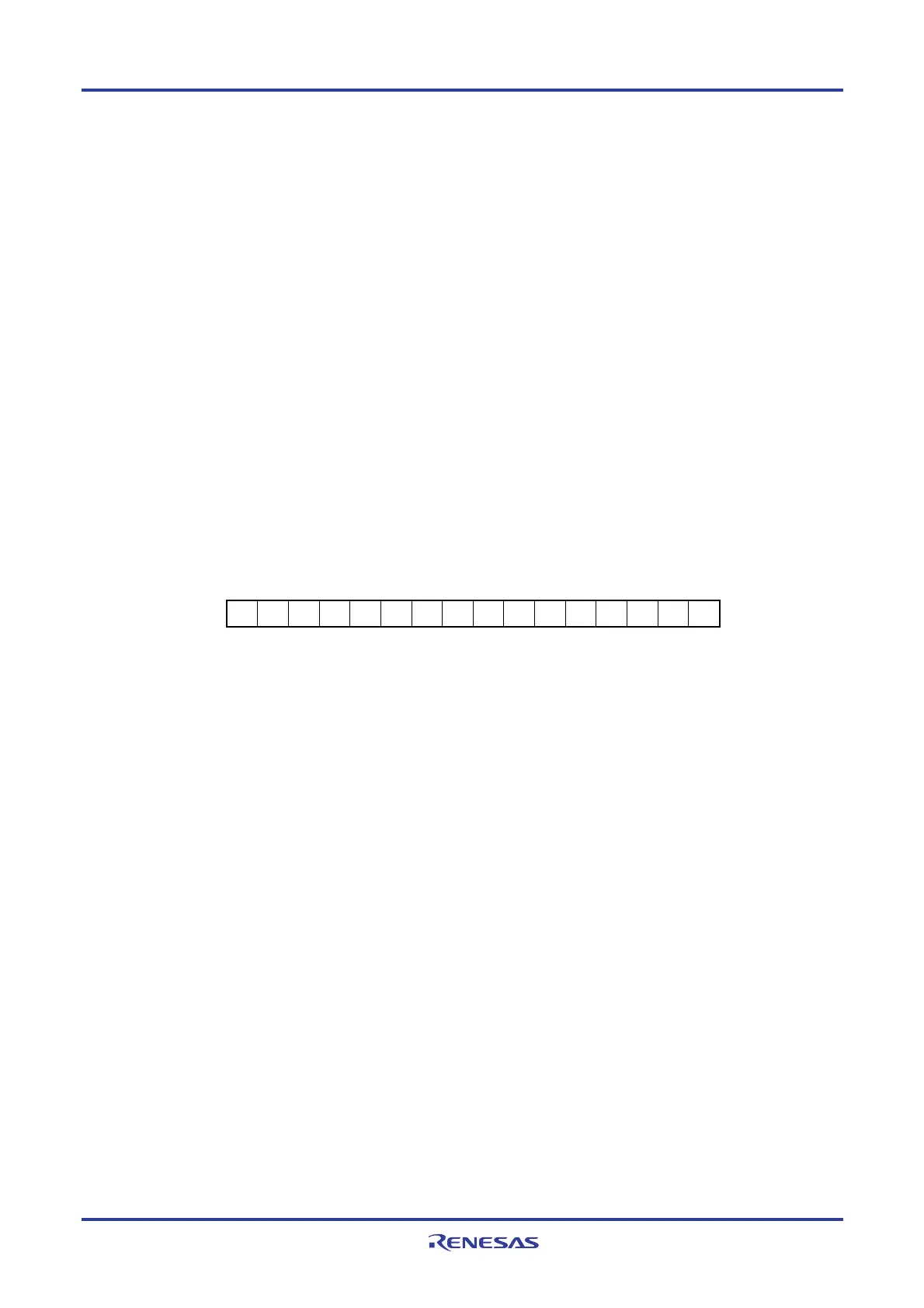
(3) Stack pointer (SP)
This is a 16-bit register to hold the start address of the memory stack area. Only the internal RAM area can be set as
the stack area.
Figure 3-24. Format of Stack Pointer
15
SP
SP15 SP14 SP13 SP12 SP11 SP10
SP9 SP8 SP7 SP6 SP5 SP4 SP3 SP2 SP1 SP0
0
The SP is decremented ahead of write (save) to the stack memory and is incremented after read (restored) from the
stack memory.
Each stack operation saves data as shown in Figure 3-25.
Cautions 1. Since reset signal generation makes the SP contents undefined, be sure to initialize the SP
before using the stack.
2. It is prohibited to use the general-purpose register (FFEE0H to FFEFFH) space as a stack area.
3. The internal RAM in the following products cannot be used as stack memory when using the
self-programming function and data flash function.
R5F100xD, R5F101xD (x = 6 to 8, A to C, E to G, J, L): FF300H to FF309H
R5F100xE, R5F101xE (x = 6 to 8, A to C, E to G, J, L): FEF00H to FF309H
R5F100xJ, R5F101xJ (x = F, G, J, L, M, P): FAF00H to FB309H
R5F100xL, R5F101xL (x = F, G, J, L, M, P, S): F7F00H to F8309H
<R>
 Loading...


