RL78/G13 CHAPTER 12 SERIAL ARRAY UNIT
R01UH0146EJ0100 Rev.1.00 573
Sep 22, 2011
12.4.2 Stopping the operation by channels
The stopping of the operation by channels is set using each of the following registers.
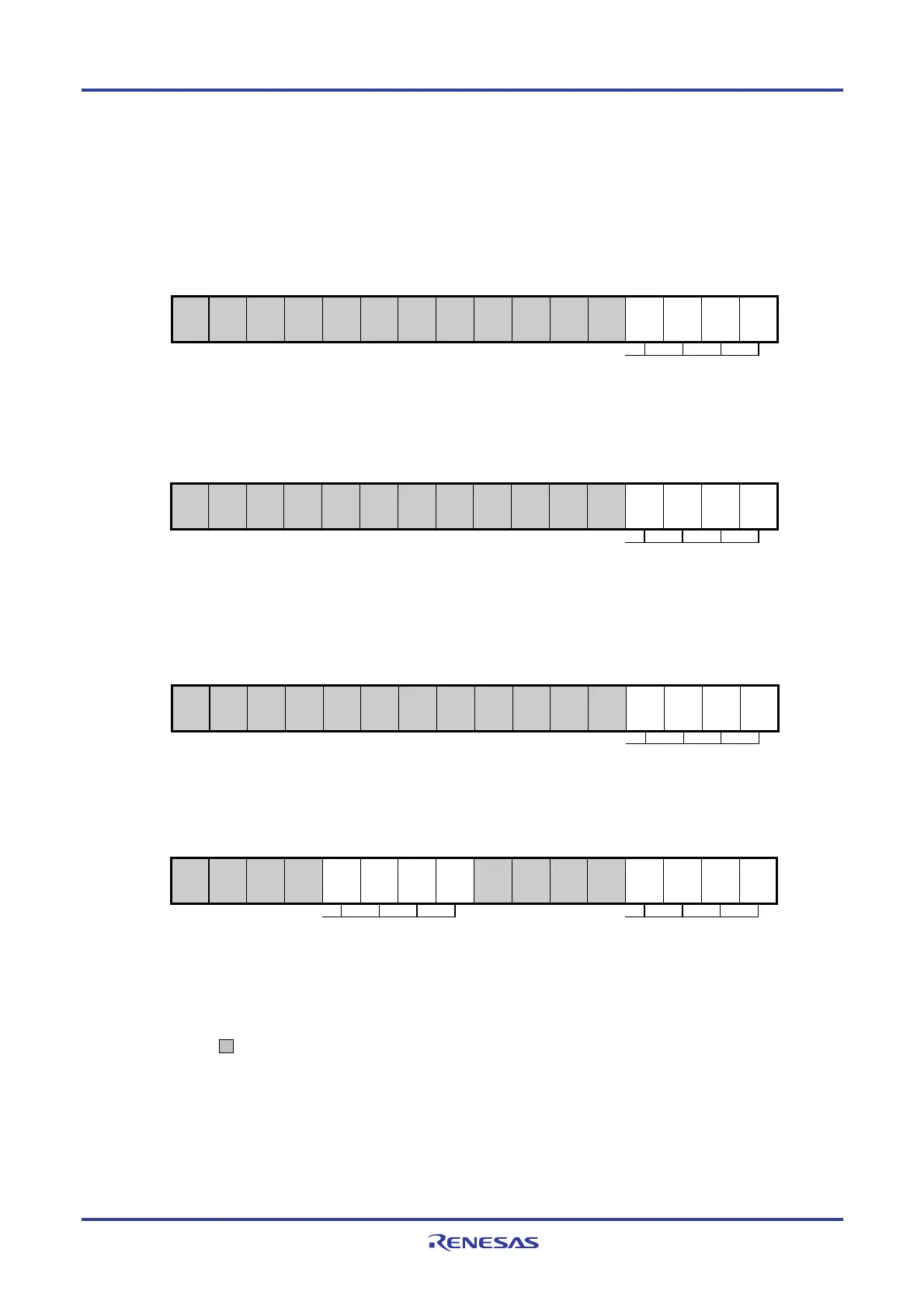
Figure 12-25. Each Register Setting When Stopping the Operation by Channels
(a) Serial channel stop register m (STm) … This register is a trigger register that is used to enable
stopping communication/count by each channel.
15 14 13 12 11 10 9 8 7 6 5 4 3 2 1 0
STm
0
0
0
0
0
0
0
0
0
0
0
0
STm3
Note
0/1
STm2
Note
0/1
STm1
0/1
STm0
0/1
1: Clears the SEmn bit to 0 and stops the communication operation
* Because the STmn bit is a trigger bit, it is cleared immediately when SEmn = 0.
(b) Serial Channel Enable Status Register m (SEm) … This register indicates whether data
transmission/reception operation of each channel is enabled or stopped.
15 14 13 12 11 10 9 8 7 6 5 4 3 2 1 0
SEm
0
0
0
0
0
0
0
0
0
0
0
0
SEm3
Note
0/1
SEm2
Note
0/1
SEm1
0/1
SEm0
0/1
0: Operation stops
* The SEm register is a read-only status register, whose operation is stopped by using the STm register.
With a channel whose operation is stopped, the value of the CKOmn bit of the SOm register can be set by
software.
(c) Serial output enable register m (SOEm) … This register is a register that is used to enable or stop
output of the serial communication operation of each channel.
15 14 13 12 11 10 9 8 7 6 5 4 3 2 1 0
SOEm
0
0
0
0
0
0
0
0
0
0
0
0
SOEm3
Note
0/1
SOEm2
Note
0/1
SOEm1
0/1
SOEm0
0/1
0: Stops output by serial communication operation
* For channel n, whose serial output is stopped, the SOmn bit value of the SOm register can be set by software.
(d) Serial output register m (SOm) …This register is a buffer register for serial output of each channel.
15 14 13 12 11 10 9 8 7 6 5 4 3 2 1 0
SOm
0
0
0
0
CKOm3
Note
0/1
CKOm2
Note
0/1
CKOm1
0/1
CKOm0
0/1
0
0
0
0
SOm3
Note
0/1
SOm2
Note
0/1
SOm1
0/1
SOm0
0/1
1: Serial clock output value is “1”
1: Serial data output value is “1”
* When using pins corresponding to each channel as port function pins, set the corresponding CKOmn, SOmn bits to “1”.
Note Serial array unit 0 only.
Remarks 1. m: Unit number (m = 0, 1), n: Channel number (n = 0 to 3)
2. : Setting disabled (fixed by hardware), 0/1: Set to 0 or 1 depending on the usage of the user

 Loading...


