RL78/G13 CHAPTER 21 VOLTAGE DETECTOR
R01UH0146EJ0100 Rev.1.00 887
Sep 22, 2011
CHAPTER 21 VOLTAGE DETECTOR
21.1 Functions of Voltage Detector
The voltage detector (LVD) has the following functions.
• The LVD circuit compares the supply voltage (V
DD) with the detection voltage (VLVIH, VLVIL), and generates an
internal reset or internal interrupt signal.
• The detection level for the power supply detection voltage (V
LVIH, VLVIL) can be selected by using the option byte as
one of 14 levels (For details, see CHAPTER 24 OPTION BYTE).
• Operable in STOP mode.
• The following three operation modes can be selected by using the option byte.
(a) Interrupt & reset mode (option byte LVIMDS1, LVIMDS0 = 1, 0)
For the two detection voltages selected by the option byte 000C1H/010C1H, the high-voltage detection level (V
LVIH)
is used for generating interrupts and ending resets, and the low-voltage detection level (VLVIL) is used for triggering
resets.
(b) Reset mode (option byte LVIMDS1, LVIMDS0 = 1, 1)
The detection voltage (V
LVI) selected by the option byte 000C1H/010C1H is used for triggering and ending resets.
(c) Interrupt mode (option byte LVIMDS1, LVIMDS0 = 0, 1)
The detection voltage (V
LVI) selected by the option byte 000C1H/010C1H is used for generating interrupts/reset
release.
Two detection voltages (V
LVIH, VLVIL) can be specified in the interrupt & reset mode, and one (VLVI) can be specified in
the reset mode and interrupt mode.
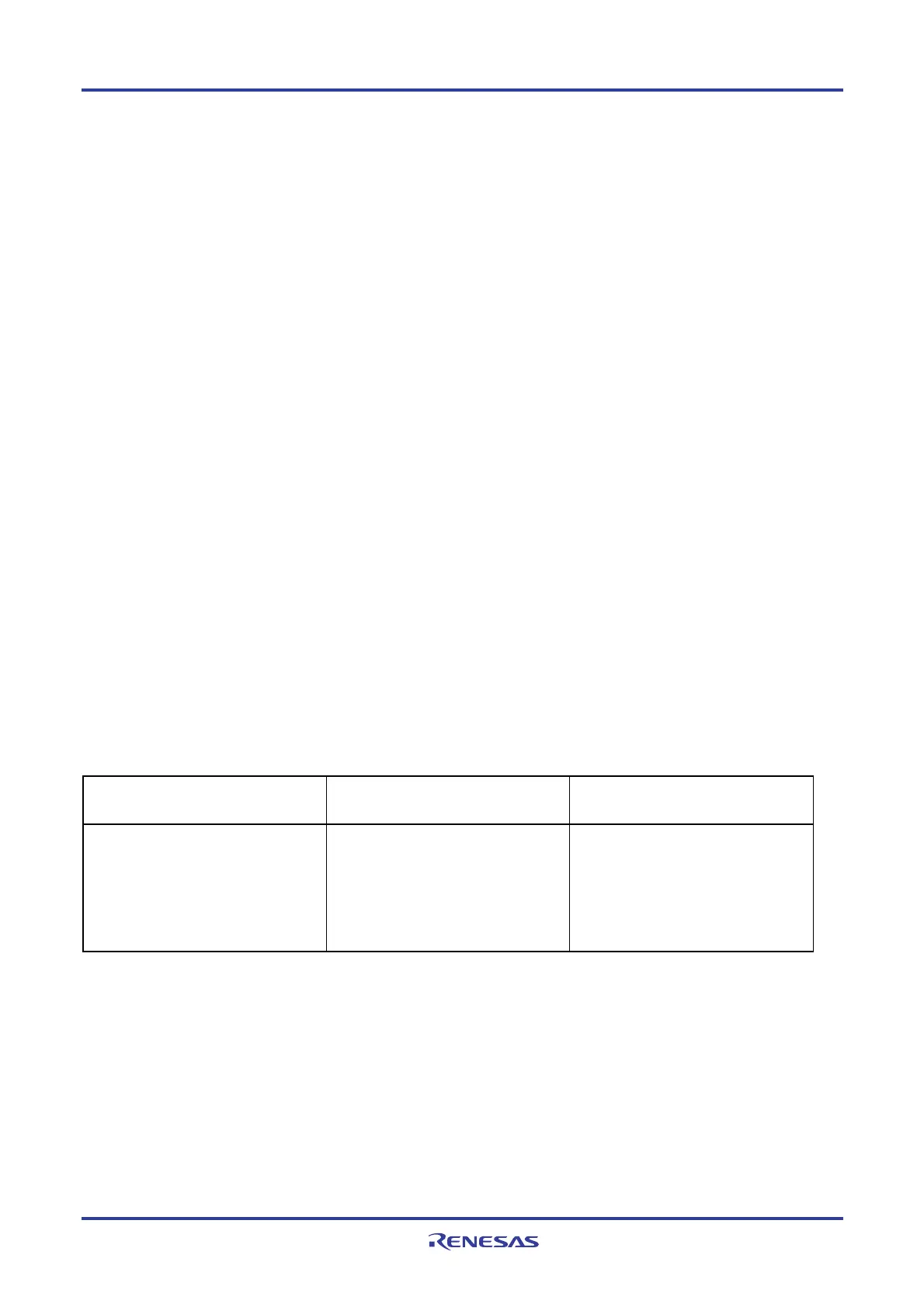
The reset and interrupt signals are generated as follows according to the option byte (LVIMDS0, LVIMDS1) selection.
Interrupt & reset mode
(LVIMDS1, LVIMDS0 = 1, 0)
Reset mode
(LVIMDS1, LVIMDS0 = 1, 1)
Interrupt mode
(LVIMDS1, LVIMDS0 = 0, 1)
Generates an internal interrupt signal
when V
DD < VLVIH, and an internal reset
when V
DD < VLVIL.
Releases the reset signal when V
DD ≥
V
LVH.
Generates an internal reset signal when
V
DD < VLVI and releases the reset signal
when V
DD ≥ VLVI.
Generates an internal interrupt signal
when V
DD drops lower than VLVI (VDD <
V
LVI) or when VDD becomes VLVI or higher
(V
DD ≥ VLVI).
Releases the reset signal when V
DD ≥ VLVI
at power on.
While the voltage detector is operating, whether the supply voltage or the input voltage from an external input pin is
more than or less than the detection level can be checked by reading the voltage detection flag (LVIF: bit 0 of the voltage
detection register (LVIM)).
Bit 0 (LVIRF) of the reset control flag register (RESF) is set to 1 if reset occurs. For details of the RESF register, see
CHAPTER 19 RESET FUNCTION.
<R>
<R>