RL78/G13 CHAPTER 23 REGULATOR
R01UH0146EJ0100 Rev.1.00 920
Sep 22, 2011
CHAPTER 23 REGULATOR
23.1 Regulator Overview
The RL78/G13 contains a circuit for operating the device with a constant voltage. At this time, in order to stabilize the
regulator output voltage, connect the REGC pin to V
SS via a capacitor (0.47 to 1
μ
F). Also, use a capacitor with good
characteristics, since it is used to stabilize internal voltage.
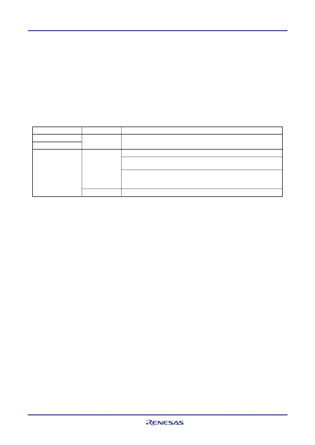
The regulator output voltage, see table 23-1.
Table 23-1. Regulator Output Voltage Conditions
Mode Output Voltage Condition
Low voltage main mode
Low-speed main mode
1.8 V -
In STOP mode
When both the high-speed system clock (fMX) and the high-speed on-chip oscillator
clock (f
IH) are stopped during CPU operation with the subsystem clock (fXT)
1.8 V
When both the high-speed system clock (f
MX) and the high-speed on-chip oscillator
clock (f
IH) are stopped during the HALT mode when the CPU operation with the
subsystem clock (f
XT) has been set
High-speed main mode
2.1 V
Other than above (include during OCD mode)
Note
Note When it shifts to the subsystem clock operation or STOP mode during the on-chip debugging, the regulator output
voltage is kept at 2.1 V (not decline to 1.8 V).
<R>
<R>

 Loading...


