RL78/G13 CHAPTER 11 A/D CONVERTER
R01UH0146EJ0100 Rev.1.00 524
Sep 22, 2011
11.7.5 Setting up test mode
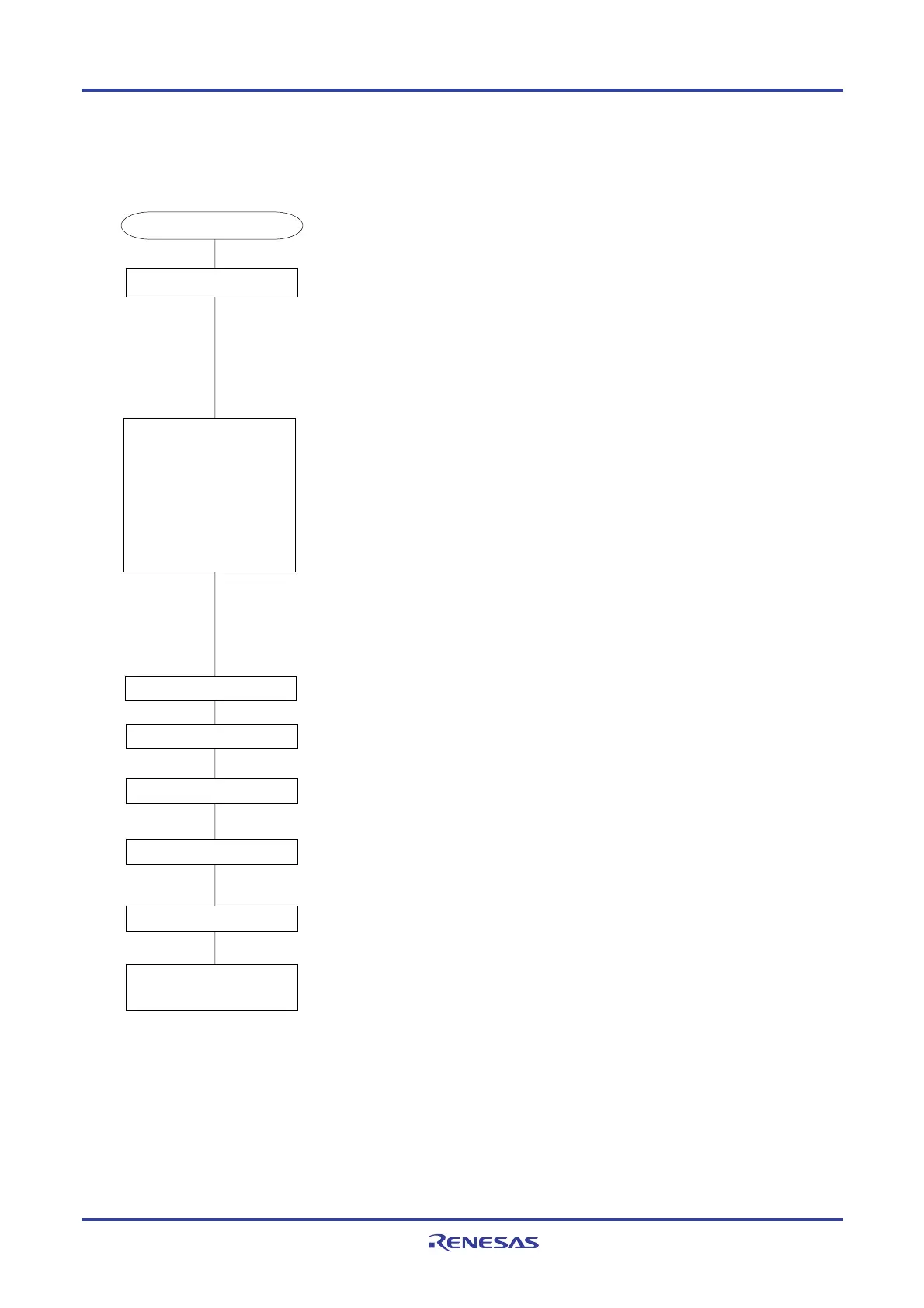
Figure 11-36. Setting up Test Trigger Mode
The ADCEN bit of the PER0 register is set (1), and supplying the clock starts.
• ADM0 register
FR2 to FR0, LV1, and LV0 bits: 11100B (set to f
CLK
/2, normal mode)
ADMD bit: This is used to s
ecif
the select mode.
• ADM1 register
ADTMD1 and ADTMD0 bits: These are used to specify the software trigger mode.
ADSCM bit: This is used to specify the one-shot conversion mode.
• ADM2 register
ADREFP1, ADREFP0, and ADREFM bits: These are used to select V
DD
and V
SS
for
the reference voltage source.
ADRCK bit: This is used to set the range for the A/D conversion result comparison
value generated by the interrupt signal to AREA2.
ADTYP bit: This is used to s
ecif
10-bit resolution.
• ADUL/ADLL register
These set ADUL to FFH and ADLL to 00H (initial values).
• ADS register
ADS4 to ADS0 bits: These are used to set to ANI0.
The A/D conversion operations are performed.
The A/D conversion end interrupt (INTAD) is generated.
Note
The conversion results are stored in the ADCR and ADCRH registers.
PER0 register setting
• ADM0 register setting
• ADM1 register setting
• ADM2 register setting
• ADUL/ADLL register setting
• ADS register setting
• ADTES register setting
(The order of the settings is
irrelevant.)
The software counts up to the stabilization wait time (1
μ
s).
Stabilization wait time count (1
μ
s)
Start of A/D conversion
End of A/D conversion
Storage of conversion results in
the ADCR and ADCRH registers
The ADCE bit of the ADM0 register is set (1), and the system enters the A/D
conversion standby status.
ADCE bit setting
ADCS bit setting
After counting up to the stabilization wait time ends, the ADCS bit of the ADM0 register
is set (1), and A/D conversion starts.
• ADTES register
ADTES1, ADTES0 bits: AV
REFM
/AV
REFP
Start of setup
Note Depending on the settings of the ADRCK bit and ADUL/ADLL register, there is a possibility of no interrupt signal
being generated. In this case, the results are not stored in the ADCR, ADCRH registers.

 Loading...


