RL78/G13 CHAPTER 15 DMA CONTROLLER
R01UH0146EJ0100 Rev.1.00 801
Sep 22, 2011
15.2 Configuration of DMA Controller
The DMA controller includes the following hardware.
Table 15-1. Configuration of DMA Controller
Item Configuration
Address registers
• DMA SFR address registers 0 to 3 (DSA0 to DSA3)
• DMA RAM address registers 0 to 3 (DRA0 to DRA3)
Count register • DMA byte count registers 0 to 3 (DBC0 to DBC3)
Control registers
• DMA mode control registers 0 to 3 (DMC0 to DMC3)
• DMA operation control register 0 to 3 (DRC0 to DRC3)
(1) DMA SFR address register n (DSAn)
This is an 8-bit register that is used to set an SFR address that is the transfer source or destination of DMA
channel n.
Set the lower 8 bits of the SFR addresses FFF00H to FFFFFH.
This register is not automatically incremented but fixed to a specific value.
In the 16-bit transfer mode, the least significant bit is ignored and is treated as an even address.
The DSAn register can be read or written in 8-bit units. However, it cannot be written during DMA transfer.
Reset signal generation clears this register to 00H.
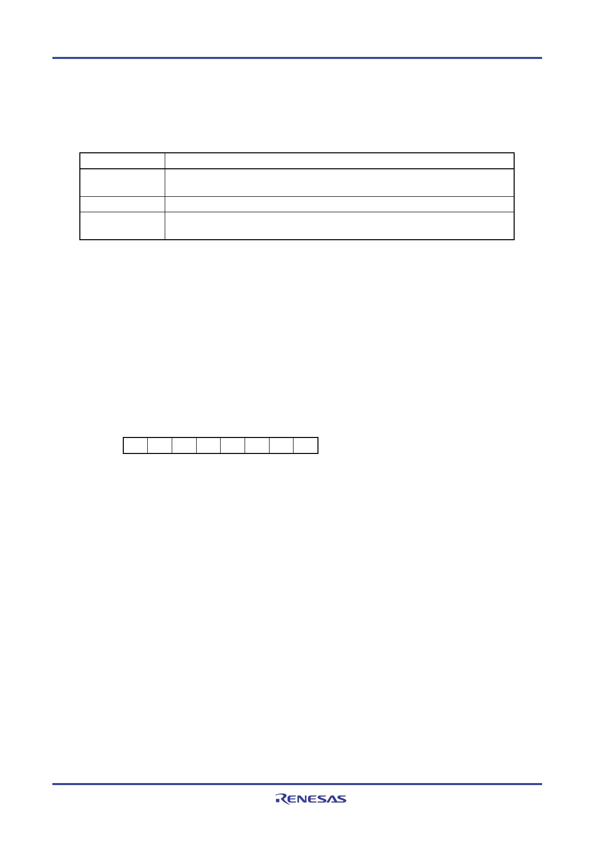
Figure 15-1. Format of DMA SFR Address Register n (DSAn)
Address: FFFB0H (DSA0), FFFB1H (DSA1), F0200H (DSA2), F0201H (DSA3) After reset: 00H R/W
7 6 5 4 3 2 1 0
DSAn
Remark n: DMA channel number (n = 0 to 3)