RL78/G13 CHAPTER 12 SERIAL ARRAY UNIT
R01UH0146EJ0100 Rev.1.00 671
Sep 22, 2011
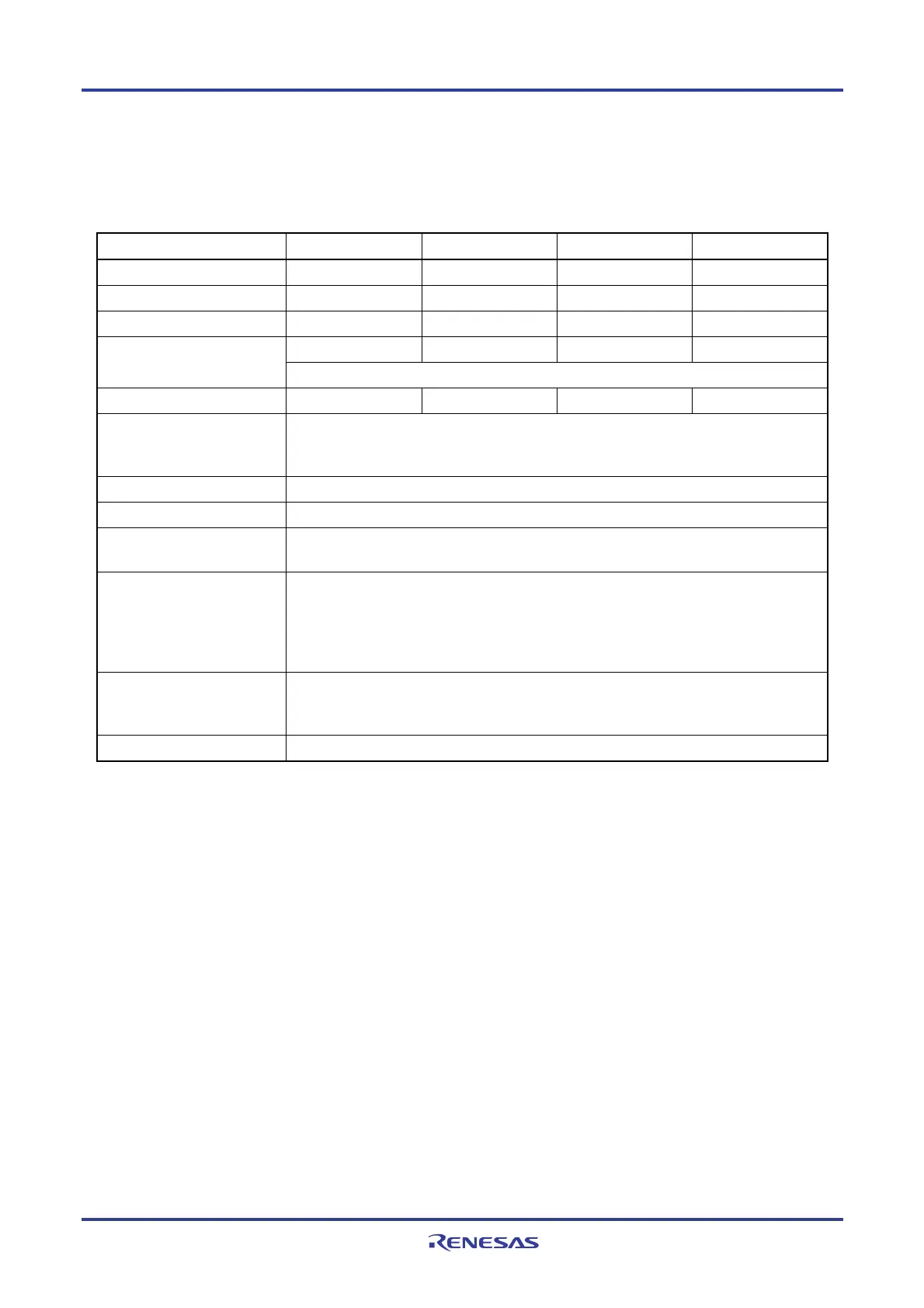
12.7.2 LIN reception
Of UART reception, UART2 of the 30, 32, 36, 40, 44, 48, 52, 64, 80, 100, and 128-pin products support LIN
communication.
For LIN reception, channel 1 of unit 1 is used.
UART UART0 UART1 UART2 UART3
Support of LIN communication Not supported Not supported Supported Not supported
Target channel
− −
Channel 1 of SAU1
−
Pins used
− −
RxD2
−
− −
INTSR2
−
Interrupt
Transfer end interrupt only (Setting the buffer empty interrupt is prohibited.)
Error interrupt
− −
INTSRE2
−
Error detection flag • Framing error detection flag (FEF11)
• Parity error detection flag (PEF11)
• Overrun error detection flag (OVF11)
Transfer data length 8 bits
Transfer rate Max. fMCK/6 [bps] (SDR11 [15:9] = 3 or more), Min. fCLK/(2 × 2
15
× 128) [bps]
Note
Data phase Forward output (default: high level)
Reverse output (default: low level)
Parity bit The following selectable
• No parity bit (The parity bit is not checked.)
• Appending 0 parity (The parity bit is not checked.)
• Even-parity check
• Odd-parity check
Stop bit The following selectable
• Appending 1 bit
• Appending 2 bits
Data direction MSB or LSB first
Note Use this operation within a range that satisfies the conditions above and the AC characteristics in the electrical
specifications (see CHAPTER 29 ELECTRICAL SPECIFICATIONS).
Remark f
MCK: Operation clock frequency of target channel
f
CLK: System clock frequency
Figure 12-101 outlines a reception operation of LIN.

 Loading...


