RL78/G13 CHAPTER 6 TIMER ARRAY UNIT
R01UH0146EJ0100 Rev.1.00 331
Sep 22, 2011
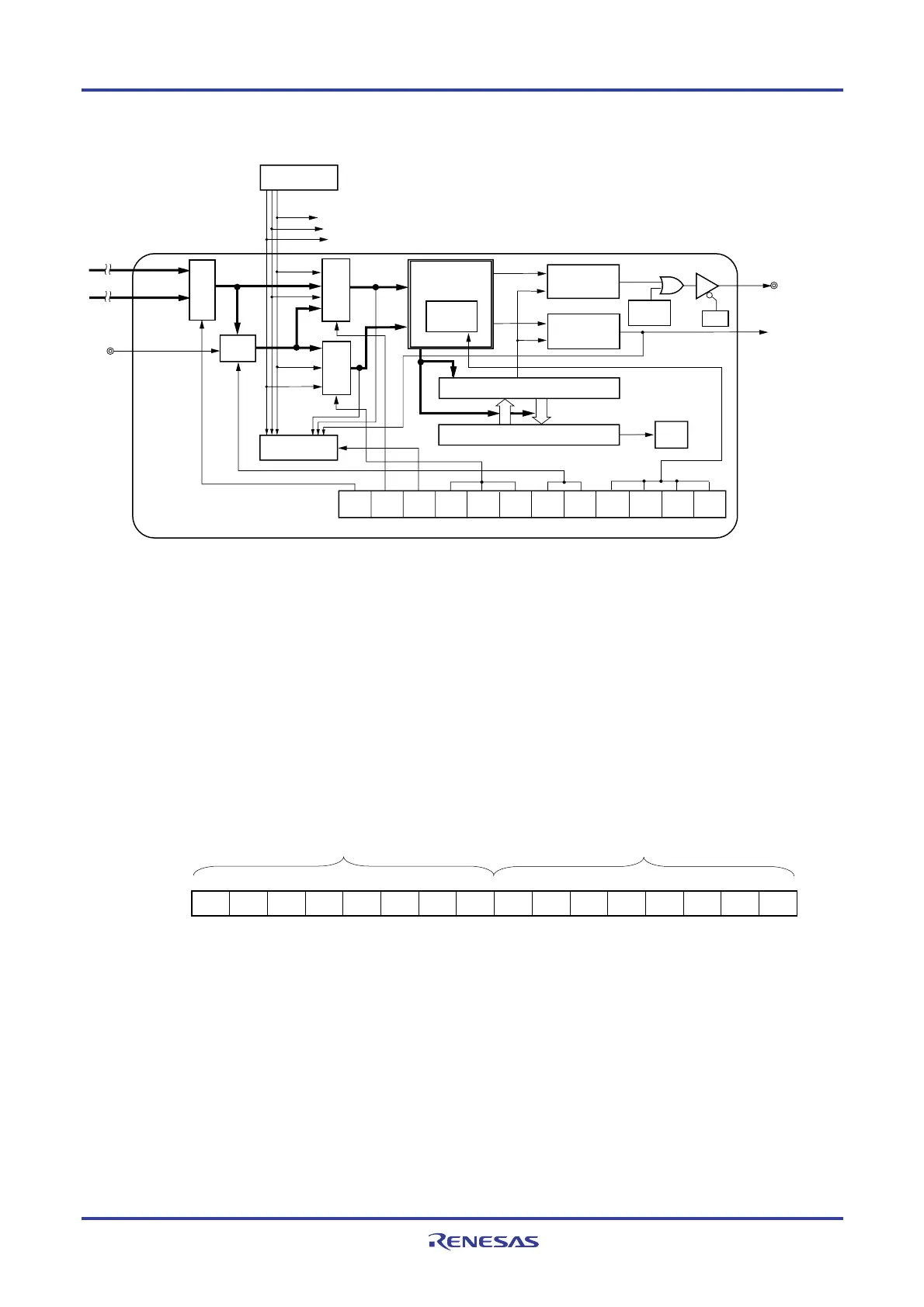
Figure 6-2. Internal Block Diagram of Channel of Timer Array Unit 0
PMxx
CKS0n
CCS0n
MAS
TER0n
STS0n2
STS0n1
STS0n0
MD0n2CIS0n1CIS0n0
MD0n3
MD0n1 MD0n0
OVF
0n
CK00
CK01
f
MCK
f
TCLK
Interrupt
controller
Output
controller
Output latch
(Pxx)
INTTM0n
(Timer interrupt)
TO0n
Timer status
register 0n (TSR0n)
Overflow
Timer data register 0n (TDR0n)
Timer counter register 0n (TCR0n)
Timer mode register 0n (TMR0n)
Channel n
Timer controller
Trigger
selection
Count clock
selection
Mode
selection
Slave/master
controller
Slave/master
controller
Edge
detection
Operating
clock selection
Trigger signal to slave channel
Clock signal to slave channel
Interrupt signal to slave channel
TI0n
Remark n = 0, 2, 4, 6
(1) Timer count register mn (TCRmn)
The TCRmn register is a 16-bit read-only register and is used to count clocks.
The value of this counter is incremented or decremented in synchronization with the rising edge of a count clock.
Whether the counter is incremented or decremented depends on the operation mode that is selected by the
MDmn3 to MDmn0 bits of timer mode register mn (TMRmn) (refer to 6.3 (3) Timer mode register mn (TMRmn)).
Figure 6-3. Format of Timer Count Register mn (TCRmn)
Address: F0180H, F0181H (TCR00) to F018EH, F018FH (TCR07), After reset: FFFFH R
F01C0H, F01C1H (TCR10) to F01CEH, F01CFH (TCR17)
15 14 13 12 11 10 9 8 7 6 5 4 3 2 1 0
TCRmn
Remark m: Unit number (m = 0, 1), n: Channel number (n = 0 to 7)
F0181H (TCR00)
F0180H (TCR00)

 Loading...


