RL78/G13 CHAPTER 6 TIMER ARRAY UNIT
R01UH0146EJ0100 Rev.1.00 367
Sep 22, 2011
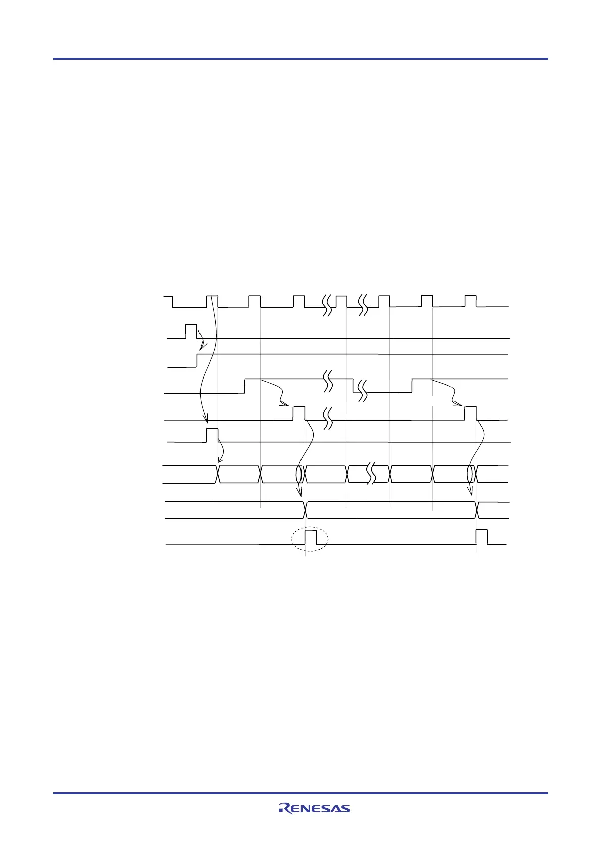
(c) Start timing in capture mode
<1> Operation is enabled (TEmn = 1) by writing 1 to the TSmn bit.
<2> Timer count register mn (TCRmn) holds the initial value until count clock generation.
<3> A start trigger is generated at the first count clock after operation is enabled. And the value of 0000H is
loaded to the TCRmn register and counting starts in the capture mode. (When the MDmn0 bit is set to 1,
INTTMmn is generated by the start trigger.)
<4> On detection of the valid edge of the TImn input, the value of the TCRmn register is captured to timer data
register mn (TDRmn) and INTTMmn is generated. However, this capture value is nomeaning. The TCRmn
register keeps on counting from 0000H.
<5> On next detection of the valid edge of the TImn input, the value of the TCRmn register is captured to timer
data register mn (TDRmn) and INTTMmn is generated.
Figure 6-25. Start Timing (In Capture Mode)
Remark The timing is shown in Figure 6-25 indicates while the noise filter is not used. By making the noise filter
on-state, the edge detection becomes 2 f
MCK cycles (it sums up to 3 to 4 cycles) later than the normal
cycle of TImn input.
Since the start of the count and the timing of TIm input are asynchronous, the first capture value (<4> in
Figure 6-24) has absolutely no connection with the pulse interval. Therefore, ignore the first capture
value.
Caution In the first cycle operation of count clock after writing the TSmn bit, an error at a maximum of one
clock is generated since count start delays until count clock has been generated. When the
information on count start timing is necessary, an interrupt can be generated at count start by
setting MDmn0 = 1.
fMC
(fTCLK)
TSmn(Write)
TEmn
TI0n input
<1>
<2>
Rising edge
Edge detection
<4>
TCRmn Initial value
m−1
m
TDRmn
Start trigger
detection signal
When MDmn0=1
setting
<3>
0000
m
Edge detection
0001
0000
INTTMmn
<5>
0000 0001
<3>
 Loading...


