RL78/G13 CHAPTER 12 SERIAL ARRAY UNIT
R01UH0146EJ0100 Rev.1.00 563
Sep 22, 2011
(13) Serial output level register m (SOLm)
The SOLm register is a register that is used to set inversion of the data output level of each channel.
This register can be set only in the UART mode. Be sure to set 0 for corresponding bit in the CSI mode and
simplifies I
2
C mode.
Inverting channel n by using this register is reflected on pin output only when serial output is enabled (SOEmn = 1).
When serial output is disabled (SOEmn = 0), the value of the SOmn bit is output as is.
Rewriting the SOLm register is prohibited when the register is in operation (when SEmn = 1).
The SOLm register can be set by a 16-bit memory manipulation instruction.
The lower 8 bits of the SOLm register can be set with an 8-bit memory manipulation instruction with SOLmL.
Reset signal generation clears the SOLm register to 0000H.
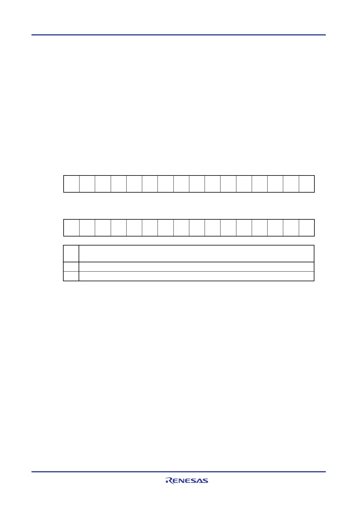
Figure 12-17. Format of Serial Output Level Register m (SOLm)
Address: F0134H, F0135H (SOL0) After reset: 0000H R/W
Symbol 15 14 13 12 11 10 9 8 7 6 5 4 3 2 1 0
SOL0 0 0 0 0 0 0 0 0 0 0 0 0 0
SOL
02
0
SOL
00
Address: F0174H, F0175H (SOL1) After reset: 0000H R/W
Symbol 15 14 13 12 11 10 9 8 7 6 5 4 3 2 1 0
SOL1 0 0 0 0 0 0 0 0 0 0 0 0 0
SOL
12
0
SOL
10
SOL
mn
Selects inversion of the level of the transmit data of channel n in UART mode
0 Communication data is output as is.
1 Communication data is inverted and output.
Caution Be sure to clear bits 15 to 3, and 1 of the SOL0 register and bits 15 to 3, and 1 of the SOL1
register to “0”.
Remark m: Unit number (m = 0, 1), n: Channel number (n = 0, 2)
<R>
 Loading...


