RL78/G13 CHAPTER 1 OUTLINE
R01UH0146EJ0100 Rev.1.00 41
Sep 22, 2011
(2/2)
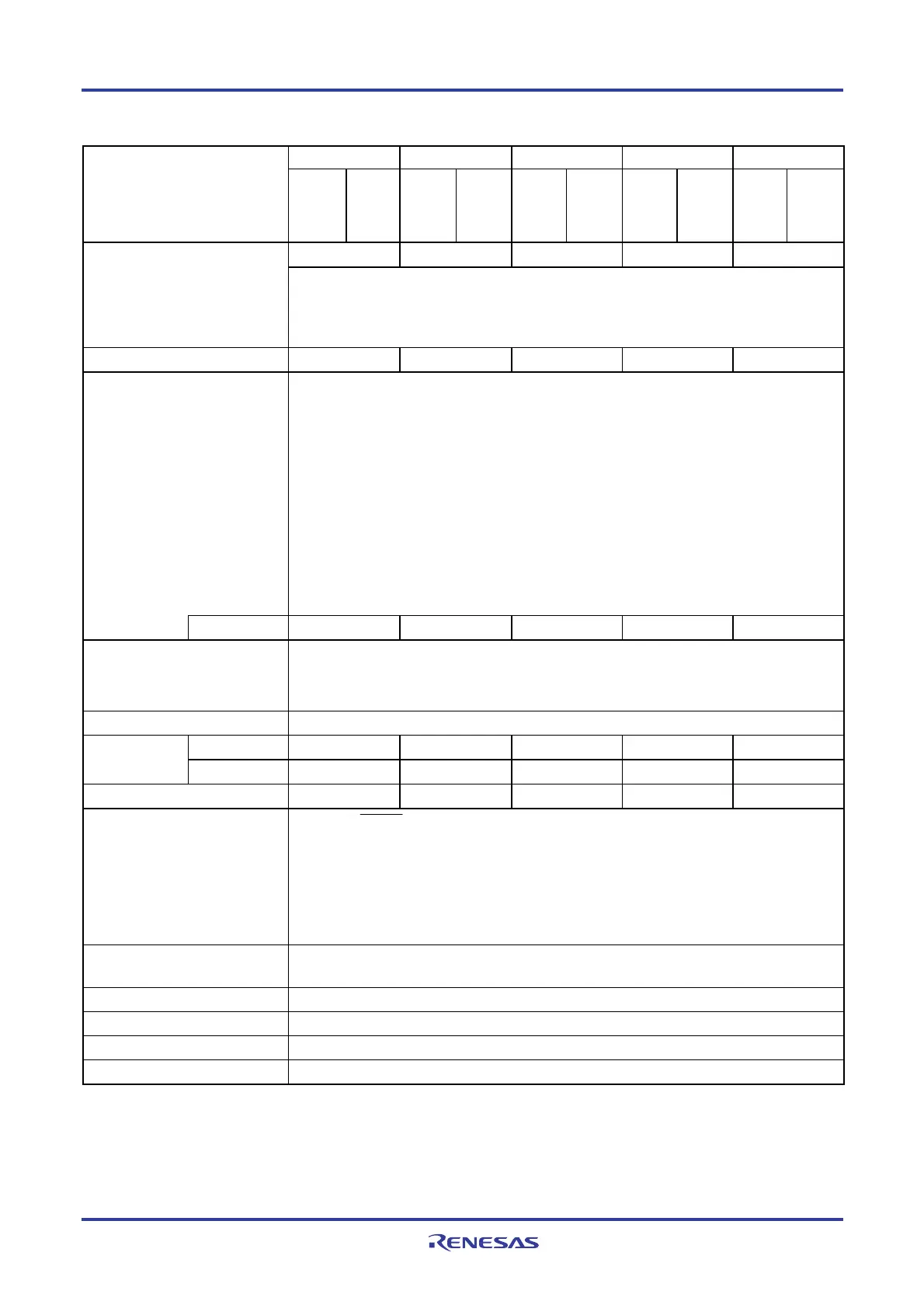
40-pin 44-pin 48-pin 52-pin 64-pin Item
R5F100Ex
R5F101Ex
R5F100Fx
R5F101Fx
R5F100Gx
R5F101Gx
R5F100Jx
R5F101Jx
R5F100Lx
R5F101Lx
2 2 2 2 2 Clock output/buzzer output
• 2.44 kHz, 4.88 kHz, 9.76 kHz, 1.25 MHz, 2.5 MHz, 5 MHz, 10 MHz
(Main system clock: f
MAIN = 20 MHz operation)
• 256 Hz, 512 Hz, 1.024 kHz, 2.048 kHz, 4.096 kHz, 8.192 kHz, 16.384 kHz, 32.768 kHz
(Subsystem clock: f
SUB = 32.768 kHz operation)
8/10-bit resolution A/D converter 9 channels 10 channels 10 channels 12 channels 12 channels
Serial interface [40-pin, 44-pin products]
• CSI: 1 channel/UART: 1 channel/simplified I
2
C: 1 channel
• CSI: 1 channel/UART: 1 channel/simplified I
2
C: 1 channel
• CSI: 2 channels/UART (UART supporting LIN-bus): 1 channel/simplified I
2
C: 2 channels
[48-pin, 52-pin products]
• CSI: 2 channels/UART: 1 channel/simplified I
2
C: 2 channels
• CSI: 1 channel/UART: 1 channel/simplified I
2
C: 1 channel
• CSI: 2 channels/UART (UART supporting LIN-bus): 1 channel/simplified I
2
C: 2 channels
[64-pin products]
• CSI: 2 channels/UART: 1 channel/simplified I
2
C: 2 channels
• CSI: 2 channels/UART: 1 channel/simplified I
2
C: 2 channels
• CSI: 2 channels/UART (UART supporting LIN-bus): 1 channel/simplified I
2
C: 2 channels
I
2
C bus 1 channel 1 channel 1 channel 1 channel 1 channel
Multiplier and divider/multiply-
accumulator
• 16 bits × 16 bits = 32 bits (Unsigned or signed)
• 32 bits ÷ 32 bits = 32 bits (Unsigned)
• 16 bits × 16 bits + 32 bits = 32 bits (Unsigned or signed)
DMA controller 2 channels
Internal 27 27 27 27 27
Vectored
interrupt sources
External 7 7 10 12 13
Key interrupt 4 4 6 8 8
Reset
• Reset by RESET pin
• Internal reset by watchdog timer
• Internal reset by power-on-reset
• Internal reset by voltage detector
• Internal reset by illegal instruction execution
Note
• Internal reset by RAM parity error
• Internal reset by illegal-memory access
Power-on-reset circuit
• Power-on-reset: 1.51 ±0.03 V
• Power-down-reset: 1.50 ±0.03 V
Voltage detector 1.63 V to 4.06 V (14 stages)
On-chip debug function Provided
Power supply voltage VDD = 1.6 to 5.5 V
Operating ambient temperature TA = −40 to +85 °C
Note The illegal instruction is generated when instruction code FFH is executed.
Reset by the illegal instruction execution not issued by emulation with the in-circuit emulator or on-chip debug
emulator.




 To Next Page