RL78/G13 CHAPTER 12 SERIAL ARRAY UNIT
R01UH0146EJ0100 Rev.1.00 622
Sep 22, 2011
(1) Register setting
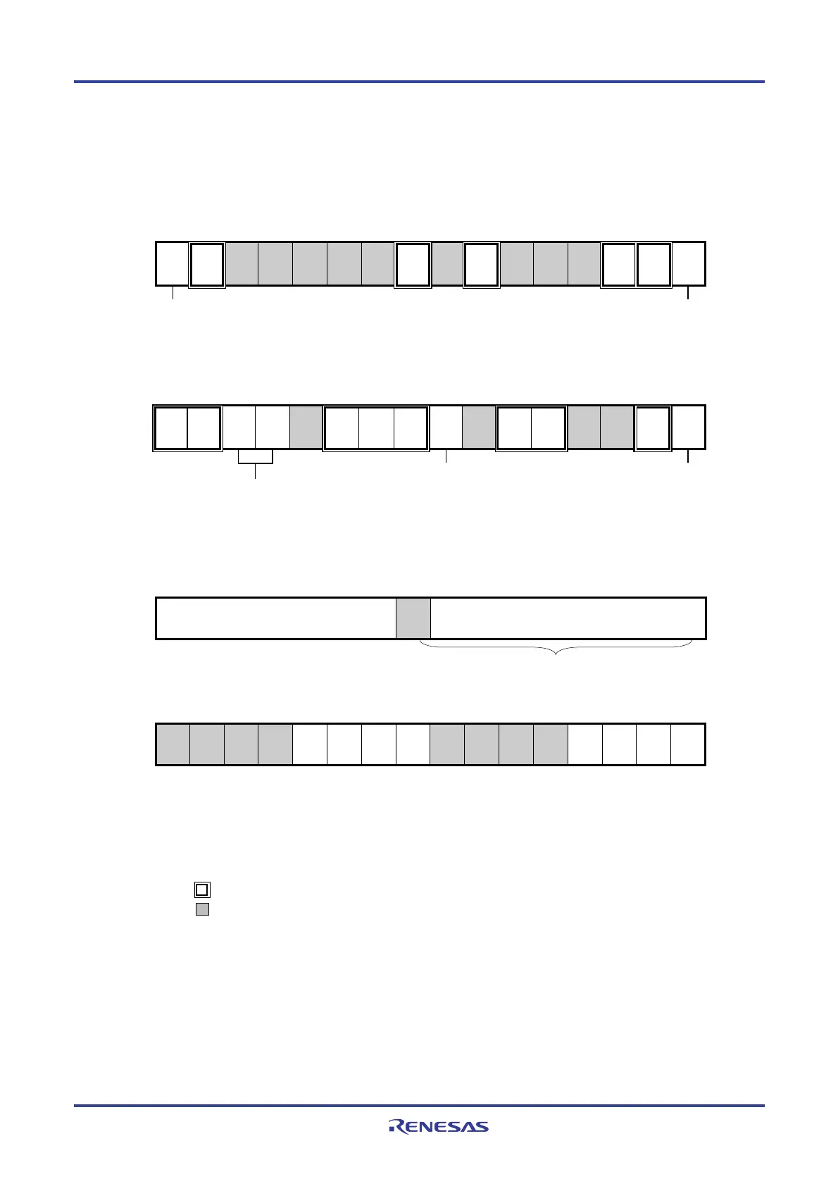
Figure 12-64. Example of Contents of Registers for Slave Transmission/Reception of 3-Wire Serial I/O
(CSI00, CSI01, CSI10, CSI11, CSI20, CSI21, CSI30, CSI31) (1/2)
(a) Serial mode register mn (SMRmn)
15 14 13 12 11 10 9 8 7 6 5 4 3 2 1 0
SMRmn
CKSmn
0/1
CCSmn
1
0
0
0
0
0
STSmn
0
0
SISmn0
0
1
0
0
MDmn2
0
MDmn1
0
MDmn0
0/1
Operation clock (fMCK) of channel n
0: Prescaler output clock CKm0 set by the SPSm register
1: Prescaler output clock CKm1 set by the SPSm register
Interrupt source of channel n
0: Transfer end interrupt
1: Buffer empty interrupt
(b) Serial communication operation setting register mn (SCRmn)
15 14 13 12 11 10 9 8 7 6 5 4 3 2 1 0
SCRmn
TXEmn
1
RXEmn
1
DAPmn
0/1
CKPmn
0/1
0
EOCmn
0
PTCmn1
0
PTCmn0
0
DIRmn
0/1
0
SLCmn1
0
SLCmn0
0
0
1
DLSmn1
1
DLSmn0
0/1
Selection of the data and clock
phase (For details about the
setting, see 12.3 Registers
Controlling Serial Array Unit.)
Selection of data transfer sequence
0: Inputs/outputs data with MSB first
1: Inputs/outputs data with LSB first.
Setting of data length
0: 7-bit data length
1: 8-bit data length
(c) Serial data register mn (SDRmn) (lower 8 bits: SIOp)
15 14 13 12 11 10 9 8 7 6 5 4 3 2 1 0
SDRmn
0000000
Baud rate setting
0
Transmit data setting/receive data register
(d) Serial output register m (SOm) … Sets only the bits of the target channel.
15 14 13 12 11 10 9 8 7 6 5 4 3 2 1 0
SOm
0
0
0
0
CKOm3
×
CKOm2
×
CKOm1
×
CKOm0
×
0
0
0
0
SOm3
0/1
SOm2
0/1
SOm1
0/1
SOm0
0/1
Caution Be sure to set transmit data to the SlOp register before the clock from the master is started.
Remarks 1. m: Unit number (m = 0, 1), n: Channel number (n = 0 to 3), p: CSI number (p = 00, 01, 10, 11, 20, 21,
30, 31), mn = 00 to 03, 10 to 13
2. : Setting is fixed in the CSI slave transmission/reception mode,
: Setting disabled (set to the initial value)
×: Bit that cannot be used in this mode (set to the initial value when not used in any mode)
0/1: Set to 0 or 1 depending on the usage of the user
SIOp