RL78/G13 CHAPTER 21 VOLTAGE DETECTOR
R01UH0146EJ0100 Rev.1.00 894
Sep 22, 2011
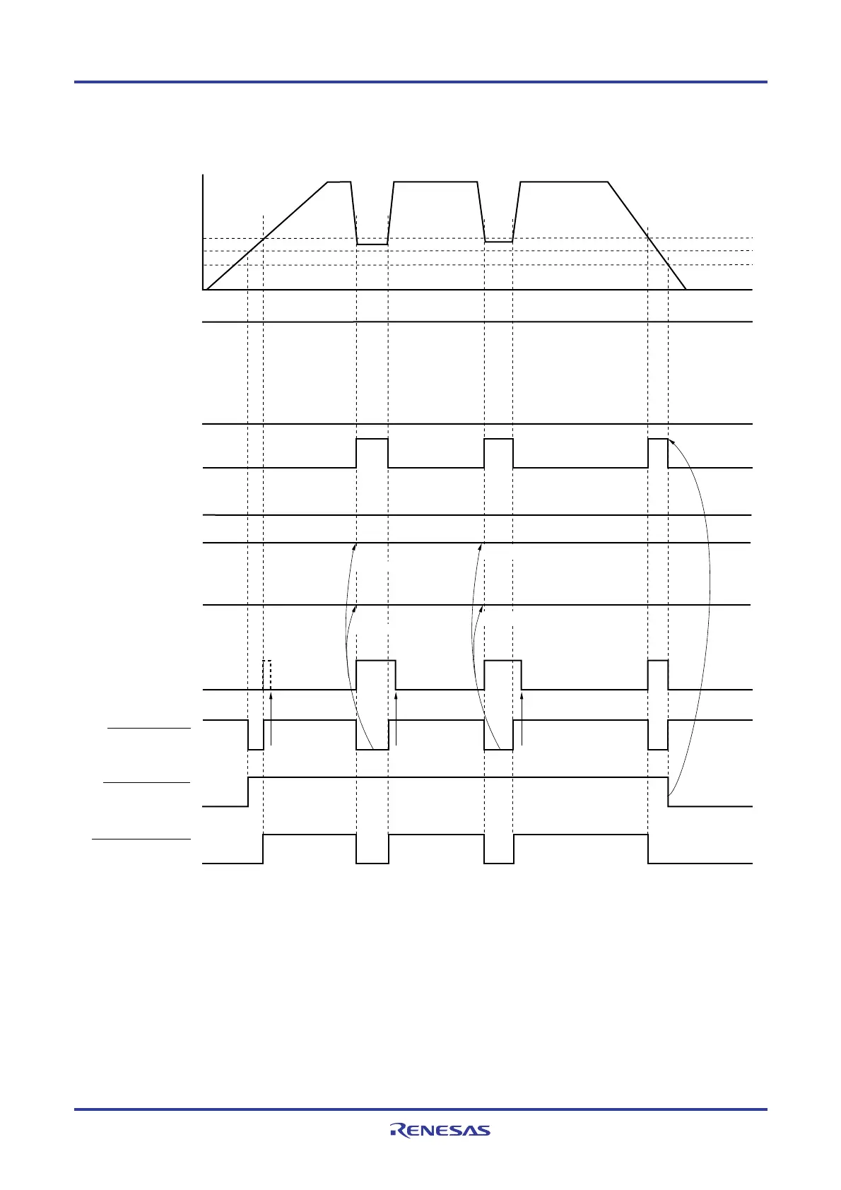
Figure 21-4. Timing of Voltage Detector Internal Reset Signal Generation
(Option Byte LVIMDS1, LVIMDS0 = 1, 1)
Internal reset signal
Supply voltage (V
DD
)
LVIMK flag
(set by software)
Time
H
Note 1
LVD reset signal
Cleared by
software
Cleared by
software
Cleared by
software
POR reset signal
Note 2
LVIOMSK flag
LVIRF flag
LVIF flag
LVISEN flag
LVIMD flag
V
LVI
VPOR = 1.51 V (TYP.)
VPDR = 1.50 V (TYP.)
H
L
LVILV flag
H
Not
cleared
Not
cleared
Not cleared
Not cleared
Cleared
Notes 1. The LVIMK flag is set to “1” by reset signal generation.
2. LVIRF flag is bit 0 of the reset control flag register (RESF).
The LVIRF flag may become 1 from the beginning due to the power-on waveform.
For details of the RESF register, see CHAPTER 19 RESET FUNCTION.
Remark V
POR: POR power supply rise detection voltage
V
PDR: POR power supply fall detection voltage
<R>

 Loading...


