32
Basic setting of the upper Z-limit switch (Z-min.; light barrier)
Fornisheddevices,thisbasic setting of the upper Z-limit switch
has already been performed. If you have checked the distance at
"Determination of the position with the smallest distance" and
this is correct, you can skip this page and continue with "Heating up
to the setting temperature".
If something changes at the printing plate later, check the distance
again and adjust it if necessary.
Before you start making your settings, check if the extruder or extrud-
ers are at the very top and contacting the extruder holder. This is a
basic prerequisite for the subsequent setting!
We recommend determining the distance settings with a gauge sheet
with 0.9 mm and one gauge sheet with 0.8 mm and 1.0 mm to be
certain.
If your printer is equipped with the dual extruder, proceed
in the same manner for the subsequent description. Set
the distance using the left extruder (viewed from the front).
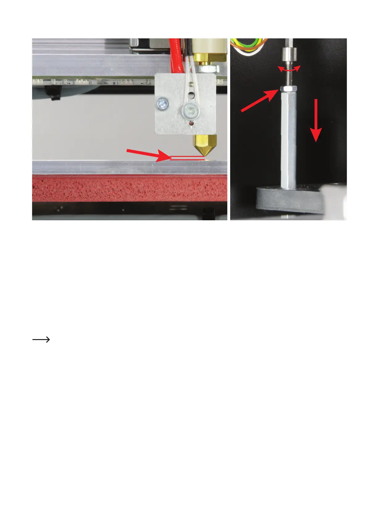
The Z-stop must be set so that there is no more than 1 mm distance
between the extruder nozzle and the printing plate. The distance
should not be any less than 0.8 mm, however. The gauge sheet with
0.9mmshouldjusttbetweenthenozzleandprintingplatewithout
application of force.
For adjustment, leave the extruder and printing plate in the position or
move it to the position where you previously determined the shortest
distance.
Move the printing plate into the Z-Home position (see "Determina-
tion of the position with the smallest distance").
Measure the distance between nozzle and printing plate. If this needs
to be corrected, move the printing plate down with the arrow button
"down" (3) until you can reach the actuation for the Z-limit switch.
Loosen the counter nut and turn the actuation for the Z-stop into the
hexagonthreadedboltinoroutuntilthedistancets.
Check the distance after 1 to 3 half turns (tighten the counter nut
manually and move it to the Z-Home position).
Then move the extruder and the printing plate manually to ensure
that the extruders cannot touch the printing plate anywhere in the
working area and that the same distance is approximately complied
with everywhere. These should never be less than 0.8 mm and not
much more than 1 mm if possible.
After this setting, counter the setting screw with the nut again.
The distance between the highest and lowest points on the printing
plate must not exceed 0.2 mm.
If the distance is larger or if you cannot make the above setting cor-
rectly,theY-plateortheundertable.
If the distance between the left and right is too large, the ball thread
drives may need to be adjusted. For this, observe chapter "12. e) As-
sembly of the mechanical basic construction" in the assembly instruc-
tions of the RF2000 v2 construction kit.
If the distance between the front and rear is not correct, the undert-
able needs to be aligned with care. The printing plate must be un-
screwedrstandtakenoffforthis,however.
min. 0,8 mm
max. 1,0 mm