13.1.4 Connection for 12V Encoder Systems
Power Supply
Data Unit Min. Typ. Max.
Voltage for encoder supply V 11,4 12 12,6
Output current mA 350
Fig.13-8: 12V Encoder Supply
Allowed Encoder Cable Lengths for 12V Encoder Systems
The maximum allowed encoder cable length for 12V encoder systems is
40 m.
Connection Diagrams for 12V Encoder Systems
For encoder supply, use lines with the same line cross section.
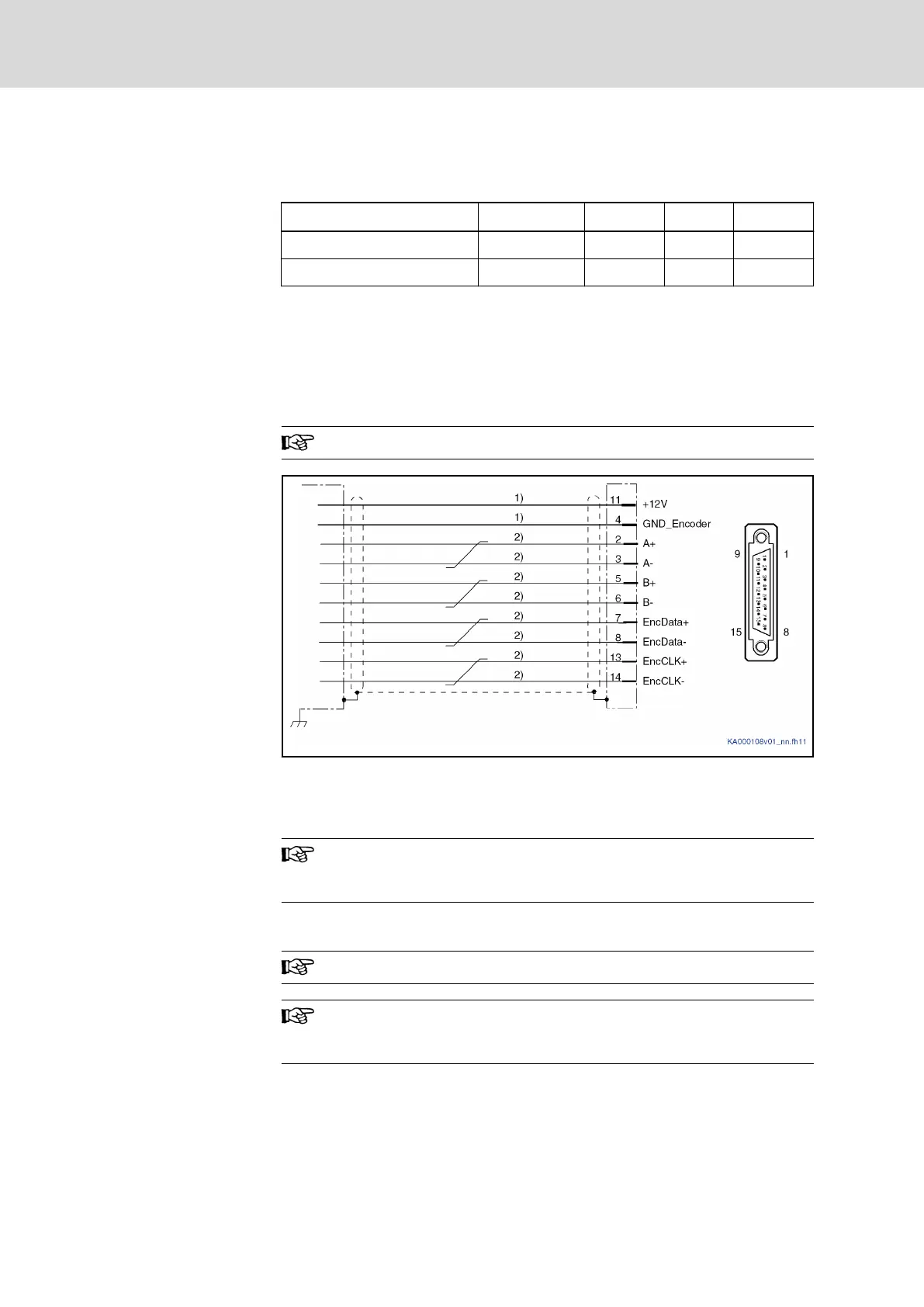
ES with "MSK/QSK Encoder Inter‐
face" for Encoder Systems S1/M1,
S2/M2, S5/M5
1) Cable cross section ≥ 0.5 mm²; observe allowed encoder cable length
2) Cable cross section ≥ 0.14 mm²
Fig.13-9: Connection Diagram "MSK/QSK Encoder Interface" for Encoder Sys‐
tems S1/M1, S2/M2, S5/M5
For direct connection to the encoder system use our cable
RKG4200. For connector type and encoder connector pin assign‐
ment, please see the cable documentation.
Connection Diagrams for 12V Third-Party Encoder Systems
For encoder supply, use lines with the same line cross section.
Observe that the third-party encoder used has to be suited for the
voltage available at the encoder evaluation ES as voltage for en‐
coder supply.
Bosch Rexroth AG DOK-INDRV*-HCQ-T+HMQ-T-PR03-EN-P
Rexroth IndraDrive Drive Controllers HCQ, HCT
122/145
Technical Data - Encoder Evaluation