4.3.3 Mounting Position
Mounting Positions of Components
Risk of damage to the components by incor‐
rect mounting position!
Only operate the components in their allowed mounting positions.
For supply units and drive controllers installed in control cabinets, only the
mounting position G1 is allowed.
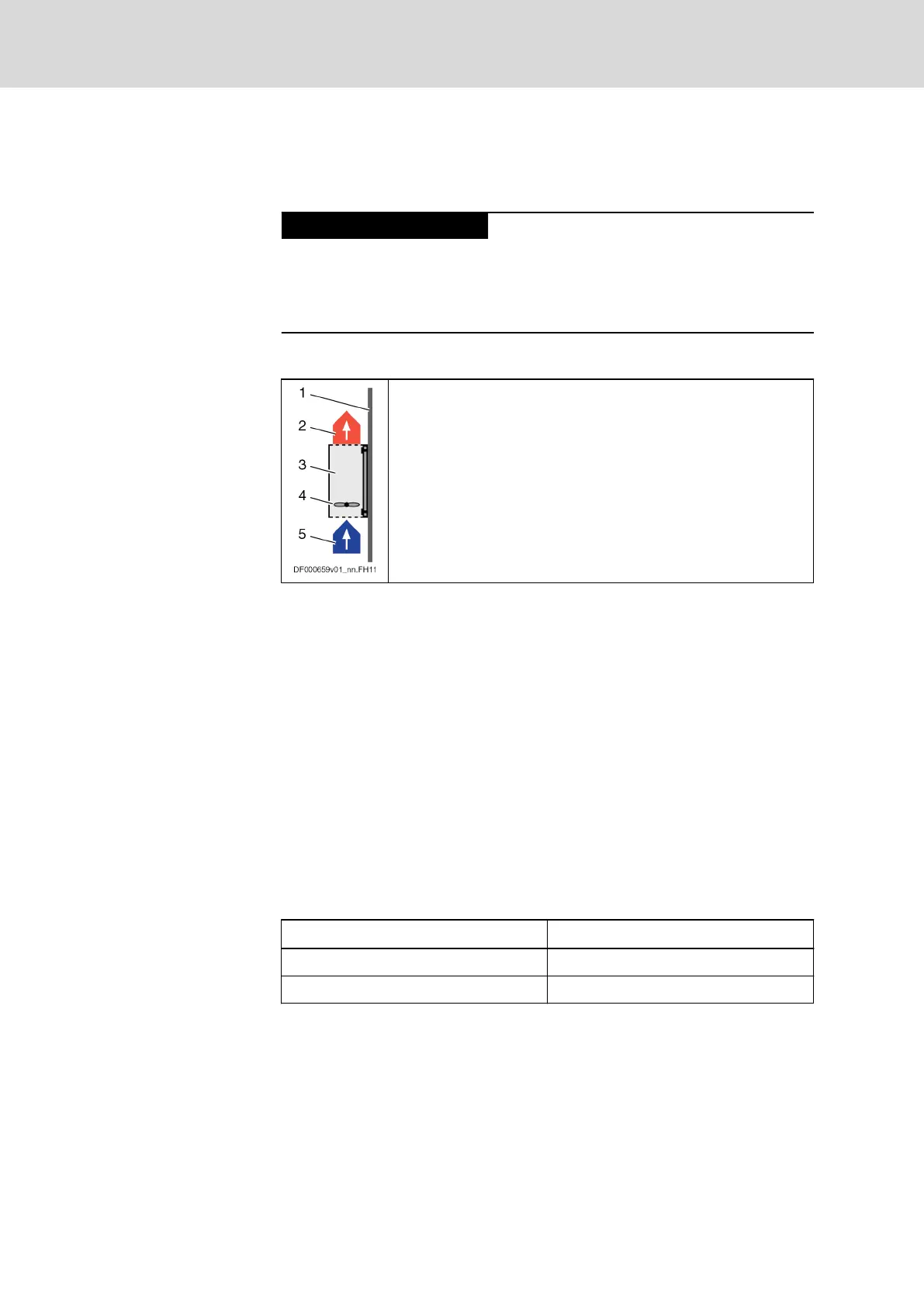
Mounting Position G1
The air that is heated inside the component can flow out of the
component in a vertical upward direction. The natural convection
supports the forced cooling air current. This avoids the generation
of pockets of heat in the component.
1. Mounting surface in control cabinet
2. Outgoing, heated air
3. Component
4. Fan within the component (forces the cooling air current)
5. Cooling air
Fig.4-9: Mounting Position G1
4.3.4 Compatibility With Foreign Matters
All Rexroth controls and drives are developed and tested according to the
state-of-the-art technology.
As it is impossible to follow the continuing development of all materials (e.g.
lubricants in machine tools) which may interact with the controls and drives, it
cannot be completely ruled out that any reactions with the materials we use
might occur.
For this reason, before using the respective material a compatibility test has
to be carried out for new lubricants, cleaning agents etc. and our housings/
materials.
4.4 Voltage Test and Insulation Resistance Test
According to standard, the components of the Rexroth IndraDrive range are
tested with voltage.
Test Test rate
Voltage test 100% (EN 61800-5-1)
Insulation resistance test 100% (EN 60204-1)
Fig.4-10: Applied Standards
Bosch Rexroth AG DOK-INDRV*-HCQ-T+HMQ-T-PR03-EN-P
Rexroth IndraDrive Drive Controllers HCQ, HCT
38/145
General Data and Specifications