2. Connect the mounting surface of the control cabinet in conductive form
to the equipment grounding system.
3. For the ground connection, observe the maximum allowed ground re‐
sistance.
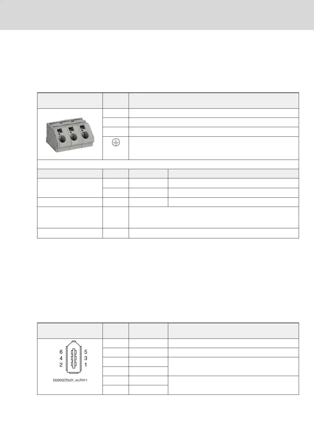
6.5 X3, Mains Connection
View Identifica‐
tion
Function
L1 Connection to supply mains phase 1 (L1)
L2 Connection to supply mains phase 2 (L2)
L3 Connection to supply mains phase 3 (L3)
Connection of equipment grounding conductor (at housing of device)
Spring terminal Unit Min. Max.
Connection cable
Stranded wire
mm
2
10 16
AWG 6 6
Stripped length mm 12 13
Occurring current load and
minimum required connec‐
tion cross section
A See technical data of device used (I
LN
and A
LN
)
Occurring voltage load V See technical data of device used (U
LN
or U
LN_nenn
)
Fig.6-5: Function, Pin Assignment, Properties
Notes on Installation
● Fuse
Fuse each phase with > 44 A
● Mains contactor
Dimension mains contactor for a rated current of 65 A
● Equipment grounding conductor
See index entry "Connection → Equipment grounding conductor"
6.6 X3L, Interface for Operator Panels
Function, Pin Assignment
Operator panels are connected via the connection point X3L.
Pin assignment Connec‐
tion
Signal name Function
1 0V
2 0V
3 USB- USB interface to operator panel
4 USB+
5 LVDS- LVDS interface to operator panel
6 LVDS+
DOK-INDRV*-HCQ-T+HMQ-T-PR03-EN-P
Rexroth IndraDrive Drive Controllers HCQ, HCT
Bosch Rexroth AG 65/145
Electrical Connection Points