6.2 Arrangement of the Connection Points
Lethal electric shock by live parts with more
than 50 V!
Connect the drive controller to the equipment grounding system via the con‐
nection points
.
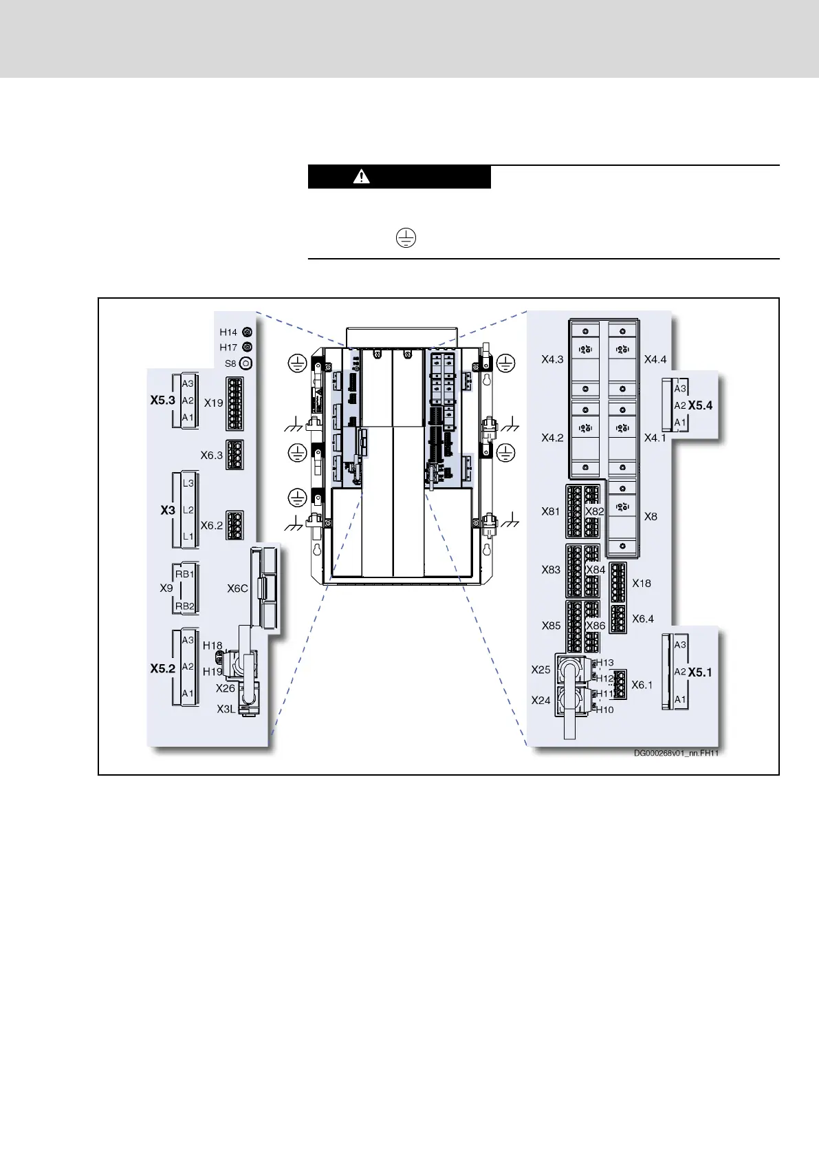
Connection Points
X3 Mains connection
X3L Interface for operator panels
X4.1…4.4 Encoder evaluation; X4.2 does not exist at 3-axis devices
X5.1…5.4 Motor connection (output inverter); X5.2 does not exist at 3-axis devi‐
ces
X6.1…6.4 Motor temperature monitoring and motor holding brake; X6.2 does not
exist at 3-axis devices
X6C Extension of memory with CompactFlash memory card
X8 Optional encoder evaluation
X9 (RB1,
RB2)
External braking and charging resistor
X18 24V supply (for control voltage and brake voltage)
X19 Bb contact, DC bus short circuit control
X24, X25 Communication
X26 Engineering interface
X81, X82 Digital outputs
X83…86 Digital inputs
Fig.6-3: Connection Points
DOK-INDRV*-HCQ-T+HMQ-T-PR03-EN-P
Rexroth IndraDrive Drive Controllers HCQ, HCT
Bosch Rexroth AG 63/145
Electrical Connection Points