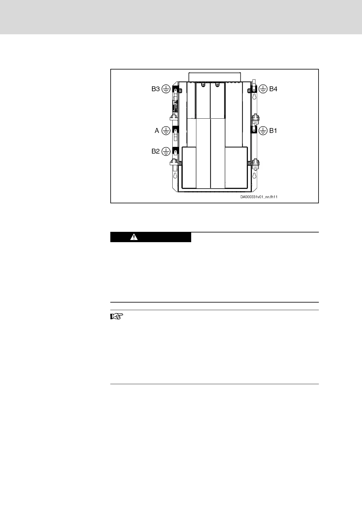
6.3 Connection of Equipment Grounding Conductor
A Mains
B1…B4 Motors (B2: Does not exist at 3-axis devices)
Fig.6-4: Connection Points of Equipment Grounding Conductor
Lethal electric shock by live parts with more
than 50 V!
Exclusively operate the device with connected equipment grounding conduc‐
tors!
Connect the equipment grounding conductor connections to the equipment
grounding system of the control cabinet.
Check the continuity of the equipment grounding conductors from the mains
connection to the connected motors.
Equipment grounding conductor: Material and cross section
For the equipment grounding conductor, use the same metal (e.g.
copper) as for the outer conductors.
For the connections from the equipment grounding conductor
connection of the device to the equipment grounding conductor
system in the control cabinet, make sure the cross sections of the
lines are sufficient.
Observe the safety instruction: Protection Against Contact With
Electrical Parts and Housings, page 23
6.4 Ground Connection
The ground connection of the housing is used to provide functional safety of
the drive controllers and protection against contact in conjunction with the
equipment grounding conductor.
Ground the housings of the drive controllers:
1. Connect the bare metal back panel of the drive controller in conductive
form to the mounting surface in the control cabinet. To do this, use the
supplied mounting screws.
Bosch Rexroth AG DOK-INDRV*-HCQ-T+HMQ-T-PR03-EN-P
Rexroth IndraDrive Drive Controllers HCQ, HCT
64/145
Electrical Connection Points
 Loading...


