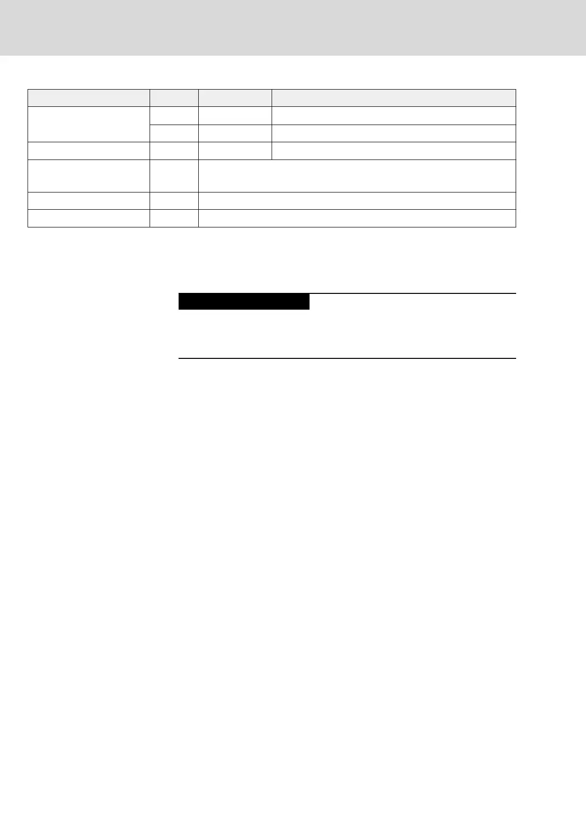
Spring terminal Unit Min. Max.
Connection cable
Stranded wire
mm
2
2,5 6
AWG 14 10
Stripped length mm 11 12
Current load A Peak value: 32
r.m.s. value: 15
Voltage load V 630
Short circuit protection To be ensured by means of appropriate fusing elements
n.s. Not specified
Fig.6-14: Function, Pin Assignment
Notes on Installation
Maximum allowed line length to external braking and charging resistor: 5 m
Twist unshielded lines.
Danger by insufficient installation!
Protect the lines with the appropriate fusing elements in the supply feeder.
For the connection lines at X9, use at least the cross section of the lines for
mains connection at X3.
Notes on Project Planning
See index entry "Braking resistor → Data, HCQ02" or "Braking resistor → Da‐
ta, HCT02"
6.14 X18, 24V Supply (Control Voltage)
Function, Pin Assignment
The external 24V supply is applied via connection point X18 for:
● Control section and power section
● Device-internal fan
● Brake control via X6
● Digital outputs at X81 and X82
Bosch Rexroth AG DOK-INDRV*-HCQ-T+HMQ-T-PR03-EN-P
Rexroth IndraDrive Drive Controllers HCQ, HCT
72/145
Electrical Connection Points