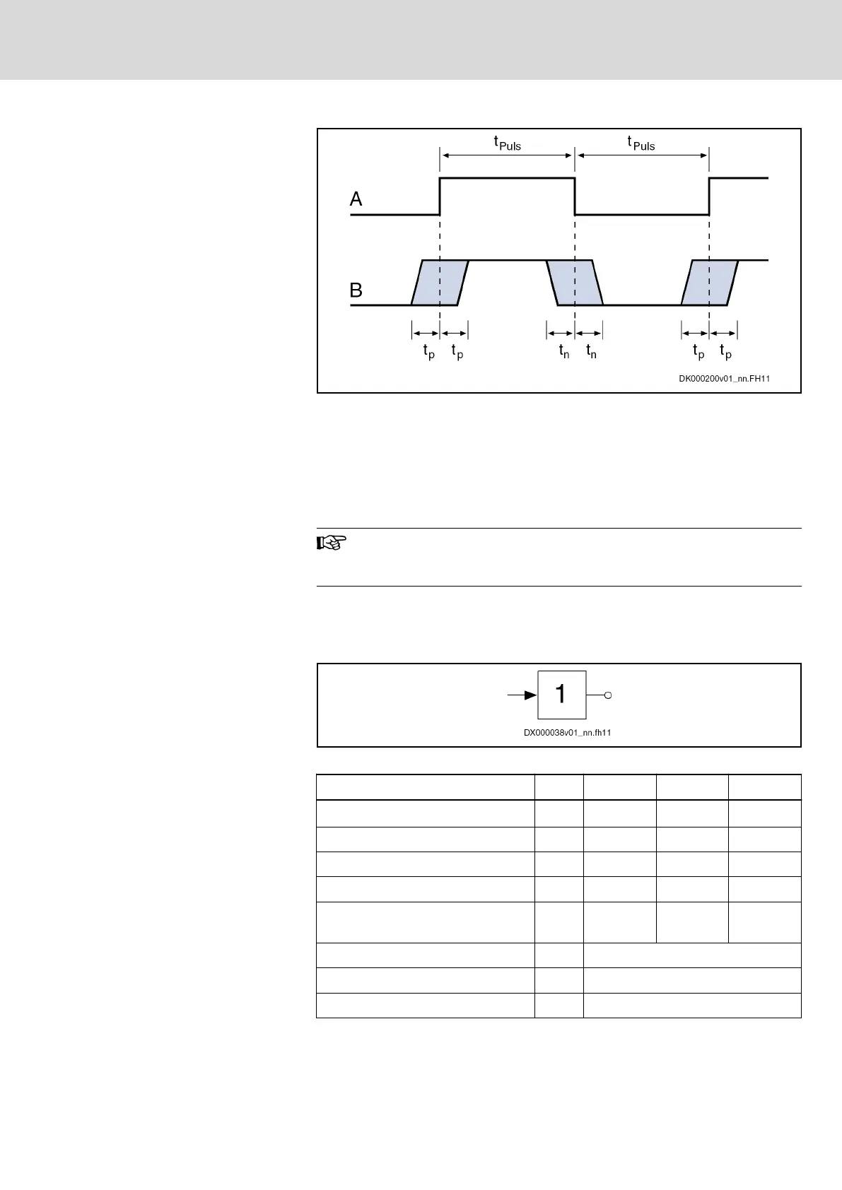
A Signal
B Signal detection at probe input
t
Puls
Pulse width
t
p
Measuring accuracy of the positive signal edge
t
n
Measuring accuracy of the negative signal edge
Fig.14-7: Signal Detection at Probe Input
Use
To acquire fast digital input signals.
Probe inputs are "fast" inputs. For control use bounce-free switch‐
ing elements (e.g. electronic switches) to avoid incorrect evalua‐
tion.
14.2.3 Digital Outputs
The digital outputs are compatible with digital inputs of types 1, 2 and 3
(IEC 61131).
Fig.14-8: Symbol
Data Unit Min. Typ. Max.
Output voltage ON V U
ext
- 0.5 24 U
ext
Output voltage OFF V 2,1
Output current OFF mA 0,05
Allowed output current per output mA 500
Allowed output current per group (8
outputs)
mA 2000
Update interval ns Depending on firmware
Short circuit protection Present
Overload protection Present
DOK-INDRV*-HCQ-T+HMQ-T-PR03-EN-P
Rexroth IndraDrive Drive Controllers HCQ, HCT
Bosch Rexroth AG 131/145
Technical Data - Functions



 To Next Page