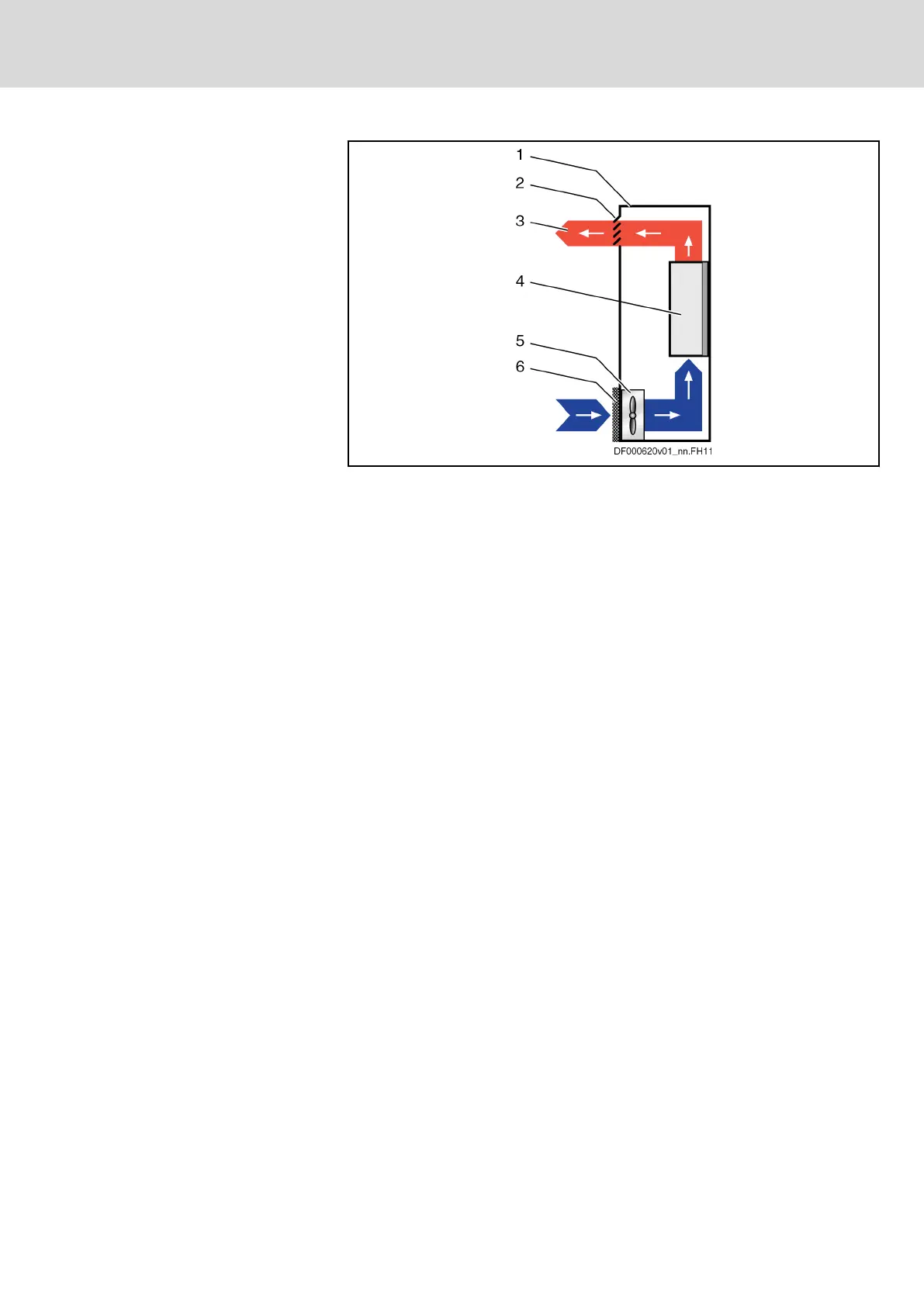
Control Cabinet Ventilation (Sche‐
matic Diagram)
1 Control cabinet
2 Air outlet opening
3 Heat discharge
4 Device in control cabinet
5 Control cabinet fan
6 Filter at air intake opening
Fig.4-8: Control Cabinet Ventilation (Schematic Diagram)
Only clean air gets into the control cabinet through the filter at the air intake
opening. The control cabinet fan behind the air intake opening delivers the air
into the control cabinet and generates overpressure in the control cabinet.
This overpressure prevents unclean air from entering into the control cabinet
through potentially leaky points (leaky cable passages, damaged seals, etc.).
DOK-INDRV*-HCQ-T+HMQ-T-PR03-EN-P
Rexroth IndraDrive Drive Controllers HCQ, HCT
Bosch Rexroth AG 37/145
General Data and Specifications
 Loading...


