Control Voltage
Project planning 24V supply
For the 24V supply, take the data on the dimensioning of the pow‐
er supply unit into account (see index entry "24V supply → Notes
on project planning").
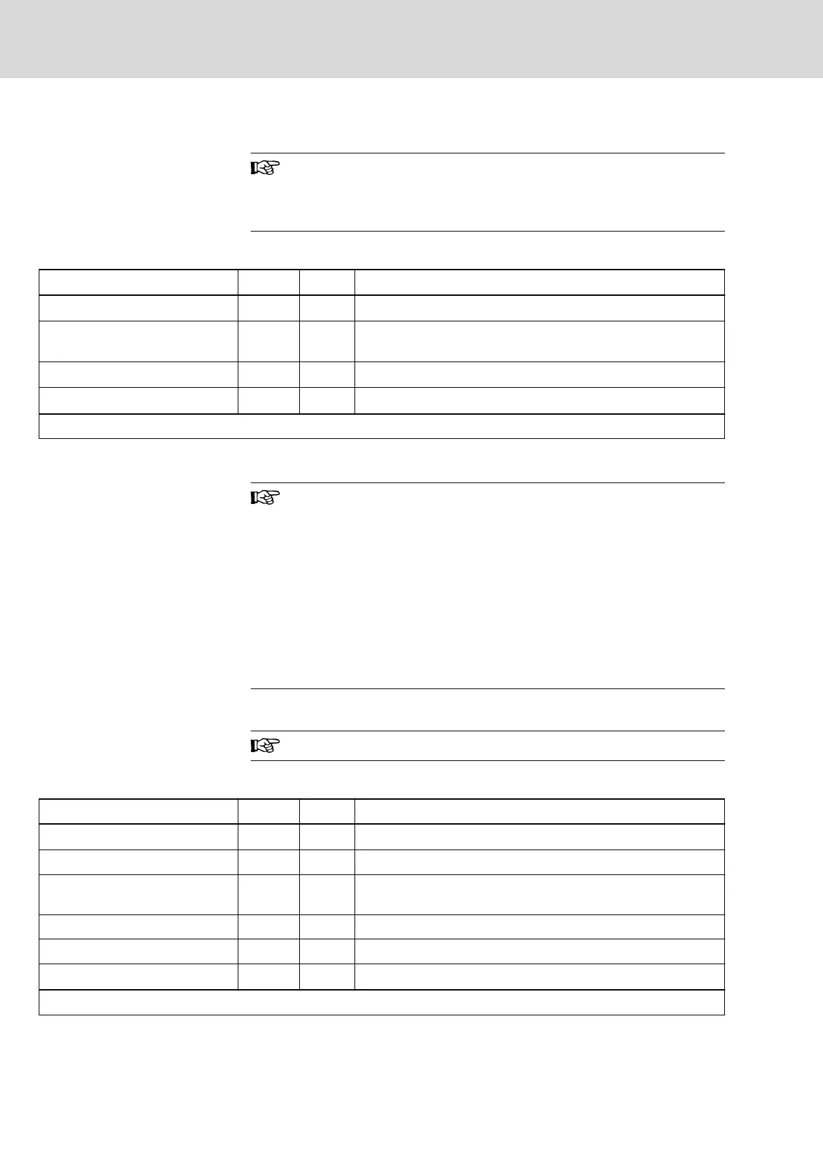
Data for Control Voltage Supply
Description Symbol Unit HCT02.1E-W0025-_-03
Rated control voltage input (UL)
1)
U
N3
V 19,2...30V
Maximum inrush current at 24V
supply
I
EIN3_max
A 13,80
Pulse width of I
EIN3
t
EIN3Lade
ms Less than 10
Input capacitance
C
N3
mF 2,64
Last modification: 2011-07-06
1) Observe supply voltage for motor holding brakes
Fig.5-20: HCT - Data for Control Voltage Supply
Overvoltage
Overvoltage greater than 33 V has to be discharged by means of
the appropriate electrical equipment of the machine or installation.
This includes:
● 24V power supply units that reduce incoming overvoltage to
the allowed value.
● Overvoltage limiters at the control cabinet input that limit ex‐
isting overvoltage to the allowed value. This, too, applies to
long 24V lines that have been run in parallel to power cables
and mains cables and can absorb overvoltage by inductive
or capacitive coupling.
Mains Voltage
The single-phase mains connection is not allowed!
Data for Mains Voltage Supply
Description Symbol Unit HCT02.1E-W0025-_-03
Input frequency (UL)
f
LN
Hz 50...60
Tolerance input frequency (UL) Hz ±2
Maximum allowed mains frequen‐
cy change
Δf
LN
/Δt
Hz/s -
Rotary field condition None
Short circuit current rating (UL) SCCR A rms 42000
Nominal mains voltage
U
LN_nenn
V 3 AC 400
Last modification: 2011-11-30
Bosch Rexroth AG DOK-INDRV*-HCQ-T+HMQ-T-PR03-EN-P
Rexroth IndraDrive Drive Controllers HCQ, HCT
54/145
Technical Data of the Components