Description Symbol Unit HCT02.1E-W0025-_-03
Monitoring value maximum DC
bus voltage, switch-off threshold
U
DC_lim‐
it_max
V 900
Charging resistor continuous pow‐
er
P
DC_Start
kW External resistor required
Allowed external DC bus capaci‐
tance (nom.) at U
LN_nenn
1)
C
DCext
mF -
Last modification: 2011-07-06
1) Use assigned type of mains choke
Fig.5-22: HCT - Data of Power Section - DC Bus
Braking Resistor
Use external resistor!
To limit the charging current when the mains voltage is connec‐
ted, the drive controller needs an external resistor (R
Softstart
).
After the mains voltage has been connected, the external resistor
is used as a braking resistor (R
DC_Bleeder
).
Project Planning of External Brak‐
ing Resistor
1. Determine the occurring continuous power and regenerative power at
the external braking resistor.
2. For this purpose, select an appropriate braking resistor; its resistance
value must be in the range of R
DC_Bleeder
.
3. Via the control unit, parameterize the data of the selected braking resis‐
tor to protect the drive controller and the braking resistor against over‐
load:
NC configuration ▶ SCSP ▶ Global ▶ ExtBrakingResistors ▶ BrakRe‐
sist[x]
Limit Values Operating Data - External Braking Resistor
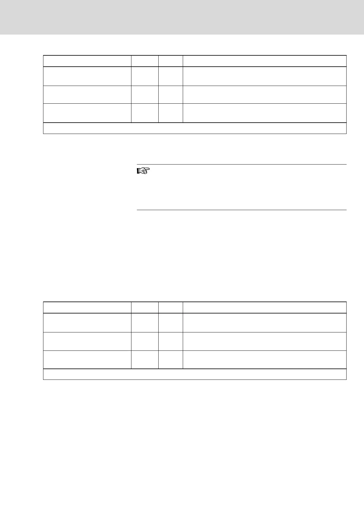
Description Symbol Unit HCT02.1E-W0025-_-03
Resistance value of external brak‐
ing resistor
1)
R
DC_Bleed‐
er
ohm 10...17
Continuous power of external
braking resistor
2)
P
BD
kW 5,00
Regenerative power to be absor‐
bed
W
R_max
kWs 100,00
Last modification: 2010-06-29
1) 2) See Parameter Description "P‑0‑0858, Data of external braking resis‐
tor"
Fig.5-23: HCT - External Braking Resistor
HLR
The following HLR braking resistors are suitable:
● HLR01.1N-0470-N11R7-A-007-NNNN
● HLR01.1N-02K0-N15R0-A-007-NNNN
● HLR01.1N-05K0-N15R0-A-007-NNNN
DOK-INDRV*-HCQ-T+HMQ-T-PR03-EN-P
Rexroth IndraDrive Drive Controllers HCQ, HCT
Bosch Rexroth AG 57/145
Technical Data of the Components
 Loading...


