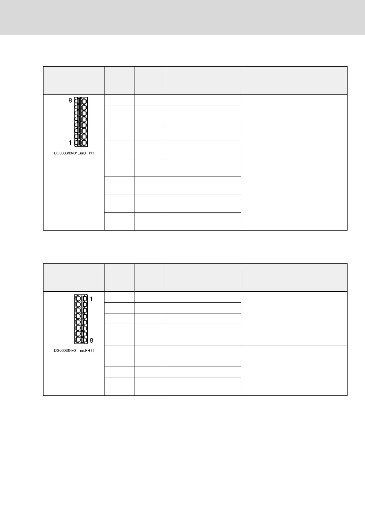
X85
View Connec‐
tion
X85
Signal
X85
Factory setting Technical Data
8 I16 The digital inputs correspond to "IEC
61131, type 1".
Reference potential 0 V: X18.4
Technical data: See index entry "Digital
inputs → Technical data"
7 I15
Travel range limit switch neg‐
ative axis 4
6 I14
Travel range limit switch pos‐
itive axis 4
5 I13
Travel range limit switch neg‐
ative axis 3
4 I12 Travel range limit switch pos‐
itive axis 3
3 I11
Travel range limit switch neg‐
ative axis 2
2 I10
Travel range limit switch pos‐
itive axis 2
1 I9
Travel range limit switch neg‐
ative axis 1
Fig.6-25: Signal Assignment X85
X86
View Connec‐
tion
X86
Signal
X86
Factory setting Technical Data
1 I1 E-Stop (all axes) The digital inputs correspond to "IEC
61131, type 1".
Can be additionally used as probes.
Reference potential 0 V: X18.4
Technical data: See index entry "Digital
inputs → Probe"
2 I2 Probe 1 (all axes)
3 I3 Probe 2 (all axes)
4 I4 Home switch axis 1
5 I5 Home switch axis 2 The digital inputs correspond to "IEC
61131, type 1".
Reference potential 0 V: X18.4
Technical data: See index entry "Digital
inputs → Technical data"
6 I6 Home switch axis 3
7 I7 Home switch axis 4
8 I8
Travel range limit switch pos‐
itive axis 1
Fig.6-26: Signal Assignment X86
DOK-INDRV*-HCQ-T+HMQ-T-PR03-EN-P
Rexroth IndraDrive Drive Controllers HCQ, HCT
Bosch Rexroth AG 81/145
Electrical Connection Points