7. Band the harness at the point [B] with the harness band included in this kit to prevent interference
with other harnesses.
8. Insert the clamp included in this kit at [D], and clamp the harness with the clamp to prevent
interference with other harnesses.
9.
Connect the harness from the counter device to CN4 [C] on the key counter interface board.
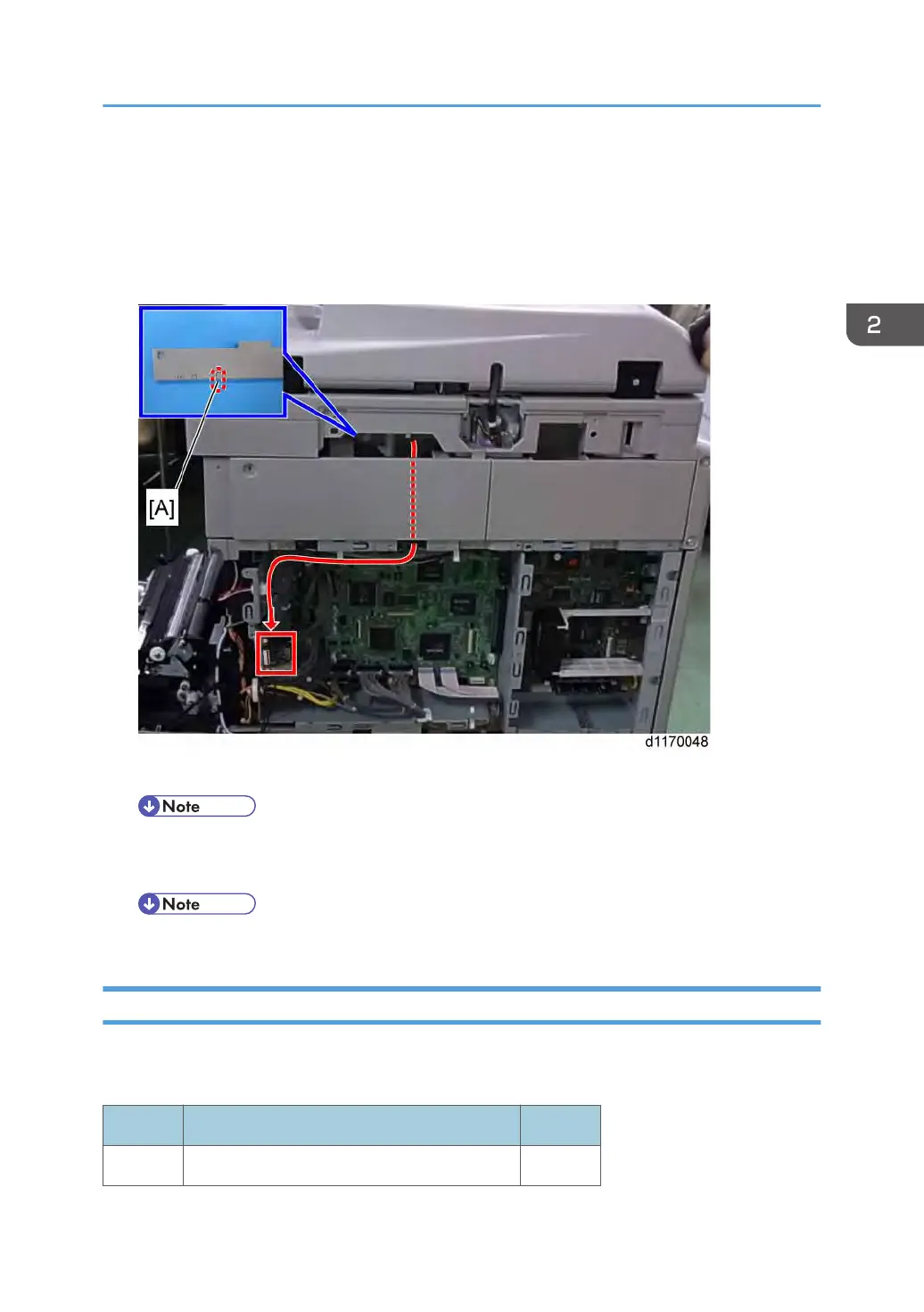
10. Route the harness.
• Remove the cutout from the scanner rear cover [A], and route the harness as shown above.
11. Reassemble the machine.
• Remove the optional counter interface unit before removing the controller box.
Mechanical Counter Installation (only for NA)
Installation of this unit requires the following components. Other components included in this kit are not
used for installation on this machine.
No. Description Q’ty
1 Mechanical Counter 1
Optional Counter Interface Unit Type A (B870)
85

 Loading...