4.1 MAINS POWER CIRCUIT
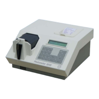
RIELE BERLIN Photometer 5010 / V4 4.1.1 28.08.2003
Function Description
The mains power circuit shows the design of the complete primary circuit. Components of the circuit are:
• Mains connector
• Mains fuses F1 and F2 ID 1707353001
• Mains switch
• AC/DC power supply ID 5010-016
• Line filter
• Ground connection
• Wires
Location
Backside of Photometer 5010, basis plate
Replacement
The Photometer 5010 has to be opened. The top case has to be separated from the bottom case.
See chapter 4.3 for replacement of AC/DC power supply.
Installation
For installation proceed in reverse order.
See also exploded view, chapter „Dismantling“
Fuses
Between the mains switch and the mains cable connector there is a cartridge with two fuses F1 and F2 with
following specifications:
• dimensions [mm] : 5 * 20
• standard: IEC 60127-2/V
• time-current characteristic: time lag (T)
• voltage rating: 250 V
• rated current: 1.6 A
• marking: T 1.6 A H