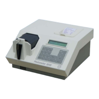
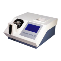
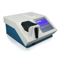
4.40 MOTHER BOARD RR-115 ID 5010-115
RIELE BERLIN Photometer 5010 / V4 4.40.1 22.09.2003
Function Description
The mother board is the central electronical unit within Photometer 5010.
Following components are equipped on the pcb:
• multiprocessorsystem based on microcontrollers SAFC517 and 87C51/52
• battery powered ram
• battery powered real time clock
• adc for photocurrent
• adc for temperature control
• stepper motor control for peristaltic pump
• stepper motor control for filter wheel
• interface infrared bubble detector
• interface RS-232C
• interface internal printer (Centronics)
• interface LCD
• interface Peltier element
• interface heating unit
• halogen lamp regulator and interface
• fuses F1, F2 and F3
Location
Basis plate
Replacement
The Photometer 5010 has to be opened. The top case has to be separated from the bottom case.
The basis plate has to be separated from the bottom case.
Disconnect all plugs from the pcb. The plugs are labled with ST1 up to ST11.
Remove five screws fixing the pcb with basis plate.
Installation
For installation proceed in reverse order.
Use heat conductor paste for getting cooling effect.
See also exploded view in chapter 5 Mantling / Dismantling.
Continue with installation instruction at the end of this chapter in case of changing a board.