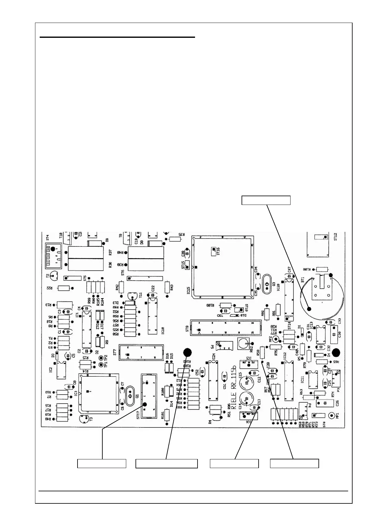
4.40 MOTHER BOARD RR-115 ID 5010-115
RIELE BERLIN Photometer 5010 / V4 4.40.3 22.09.2003
Voltages
1. Before adjustment switch off Photometer 5010. Open the instrument. Open the photometer regarding
safety rules of chapter 1 of this service manual.
2. Switch on instrument.
3. Use DVM for measuring ± 12 VDC.
4. Connect the negative lead of DVM to the ground connector (soldering connector).
5. Connect the positive lead of DVM to the cathode of diode D7.
6. Check the voltage + 12 VDC (tolerance ± 5%) at C13.
7. Connect the positive lead of DVM to the anode of diode D6.
8. Check the voltage - 12 VDC (tolerance ± 5%) at R59.
9. Connect the positive lead of DVM to the pin 11 of plug ST17.
10. Check the voltage + 5 VDC (tolerance ± 5%).
11. Connect the positive lead of DVM to the battery BT1.
12. Check the voltage + 3 VDC (tolerance ± 10%).
+ 3 VDC ± 10%
+ 12 VDC ± 5%
- 12 VDC ± 5%
Ground connector + 5 VDC ± 5%