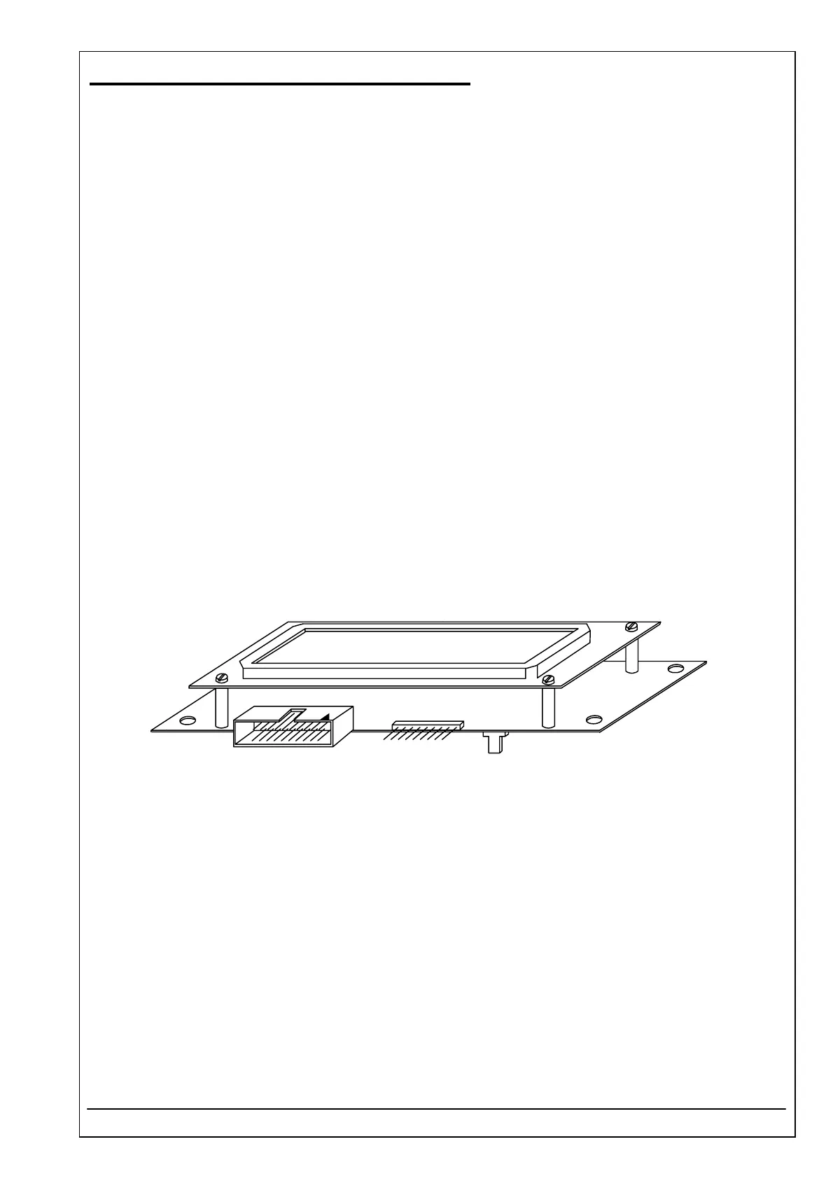
4.42 DISPLAY UNIT PCB RR-114 ID 5010-009
RIELE BERLIN Photometer 5010 / V4 4.42.1 11.05.2004
Function Description
The display unit pcb connects following components:
• LCD with 2 lines and 16 characters
• Panel with 20 keys
• Sipping lever
• PCB RR-114
Location
Basis plate
Replacement
The Photometer 5010 has to be opened. The top case has to be separated from the bottom case.
Disconnect all plugs from the pcb. The plugs are numerated with J1 up to J5.
Remove four screws fixing the pcb with top case.
Remove one screw fixing earth ground.
Installation
For installation proceed in reverse order.
See also exploded view, chapter 5.1 Mantling / Dismantling