Rockwell Automation Publication 20P-TG002B-EN-P - February 2018 115
Circuit Board Layouts and Connections Appendix B
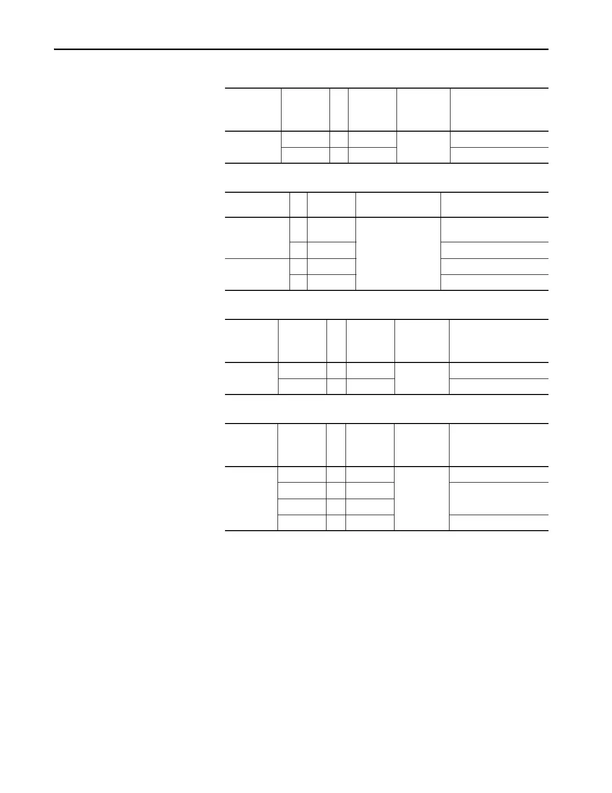
Table 20 - Pulse Transformer Board to Field Board Connections
Table 21 - Pulse Transformer Board to Switching Power Supply Connections
Table 22 - Pulse Transformer Board to Bimetal Thermostat Connections
Table 23 - Pulse Transformer Board to Field SCR/Dual Diode Module Connections
Pulse
Transformer
Board
Connector
Pin Number to Pin Number Field Board
Connector
Description
X3 1 … 1 X3 1U1 field sync signal (from U1)
2 … 2 1V1field sync signal (from V1)
Pulse Transformer
Board Point
to Pin Number Switching Power Supply
Board Connector
Description
1U2 … 4 XUV Rectified U2-V2 voltage (approx.
150/300V DC)
…3 not used
1V2 … 2 not used
…1 Common
Pulse
Transformer
Board
Connector
Pin Number to Pin Number Bimetal
Thermostat
Connector
Description
X4 1 … 1 X4 +24V supply through resistor
2…2 24V common
Pulse
Transformer
Board
Connector
Pin Number to Pin Number Field SCR/Dual
Diode Module
Connector
Description
XP1…3FastonsGate signal G1
2 … 2 Common cathode (K1 and K2) for
both field SCRs
3…2
4…1 Gate signal G2

 Loading...


