74 Rockwell Automation Publication 20P-TG002B-EN-P - February 2018
Chapter 3 Part Replacement Procedures
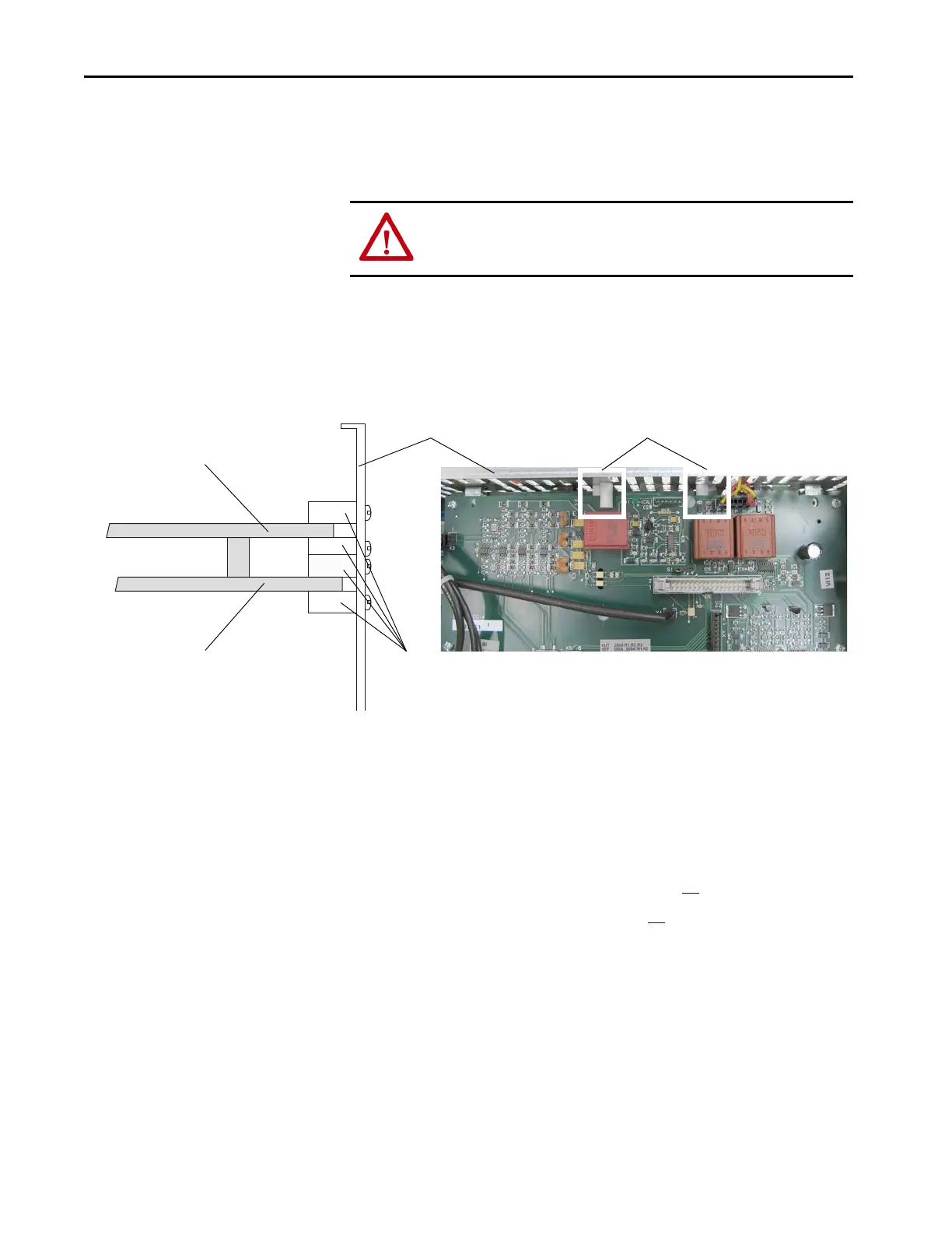
Install the Pulse Transformer and Switching Power Supply Boards
Install the new pulse transformer board in reverse order of removal.
• Verify that the four plastic board stabilizers mounted on the top air flow
plate are placed one on either side of each board.
Field Circuit Fuses
Replacement
Remove the Field Circuit Fuses
Follow these steps to remove the field circuit fuses.
1. Read the General Safety Precautions on page 10
.
2. Remove power from the drive (see page 42
).
ATTENTION: Each gate lead cable must be connected to the exact connector
from which it was removed on the pulse transformer circuit board or damage
to the drive may occur.
One plastic stabilizer should be on either side of each boardAir flow plate
Plastic
stabilizers
Top view of pulse transformer boardSide cut-away view
pulse transformer board
switching power supply board

 Loading...


