Rockwell Automation Publication 20P-TG002B-EN-P - February 2018 63
Part Replacement Procedures Chapter 3
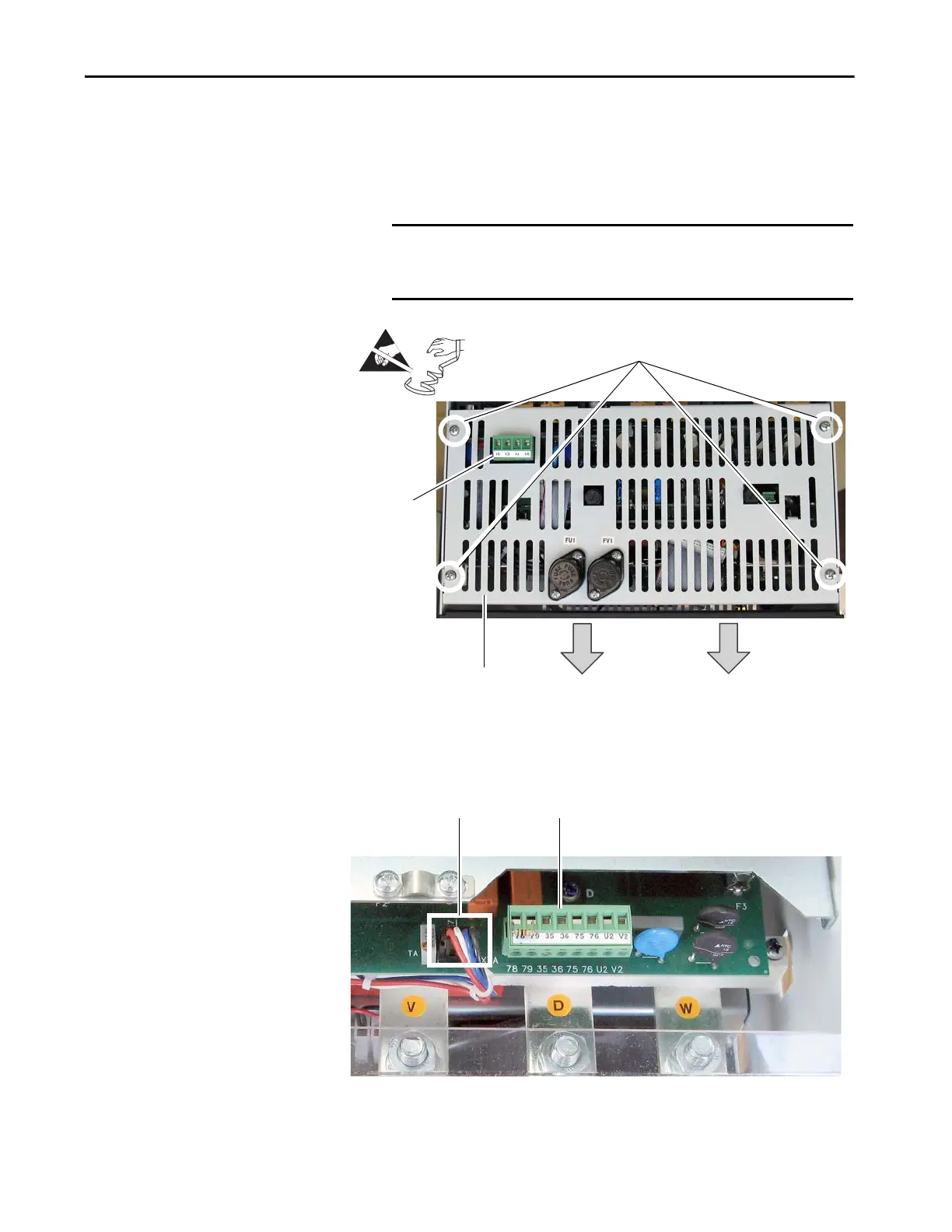
4. Remove the plug-in terminal from the field input block at the top of the
drive.
5. Remove the four screws that secure the slotted air flow plate to the top
of the drive chassis.
6. Remove the cable from connector XTA at the bottom of the pulse
transformer board.
7. Remove the plug-in terminals from the control power block at the
bottom of the pulse transformer board.
IMPORTANT The air flow plate is also secured to the pulse transformer circuit
board and therefore cannot yet be removed. Instructions for doing
so are included later in this procedure.
Air flow plate
5
4
Front of drive

 Loading...


