Rockwell Automation Publication 20P-TG002B-EN-P - February 2018 19
Component Test Procedures Chapter 2
Troubleshoot an AC
Undervoltage Fault
If the drive faults with an AC Undervoltage Fault (F4), or parameter 466 [AC
Line Voltage] does not equal the expected incoming AC line voltage, measure
the AC line input signals as directed in the steps below.
1. Read the General Safety Precautions on page 10
.
2. Remove the protective covers (see page 43
).
3. Using a voltmeter, measure the voltage at terminals U, V, and W of the
drive.
If an AC input contactor is used, the voltage must be measured on both
the input and output sides of the contactor.
If any of the voltage measurements is incorrect or missing, remove
incoming AC power and verify the wiring to the drive and the power
supply source and correct any problems.
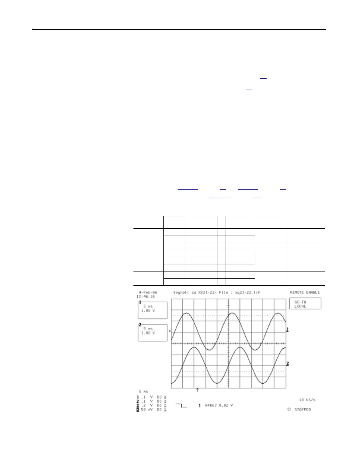
4. Using a voltmeter, measure the combined voltages of the AC lines on the
following testpoints on the control board (all waveforms have a 2.5V
offset). See Figure 1
on page 17 and Figure 2 on page 18 for location of
the testpoints. Also, see Figure 14
on page 107 for a schematic diagram.
Table 1 - Combined AC Line Input Signal Testpoints
Incoming AC
Line Voltage
Phases Measure from
Testpoint
… To Testpoint Peak to Peak
Measurement
RMS Measurement
240V AC V and U XY22 … XY18 1.42V AC 0.500V
V and W XY21 … XY18
480V AC V and U XY22 … XY18 2.95V AC 1.040V
V and W XY21 … XY18
575V AC V and U XY22 … XY18 2.85V AC 1.007V
V and W XY21 … XY18
690V AC V and U XY22 … XY18 3.45V AC 1.220V
V and W XY21 … XY18

 Loading...


