Rockwell Automation Publication 20P-TG002B-EN-P - February 2018 15
Component Test Procedures Chapter 2
Visual Component Inspection
Visually inspect the circuit boards and power components before energizing
the drive for any of the component test procedures.
1. Read the General Safety Precautions on page 10
.
2. Remove power from the drive (see page 42
).
3. Remove the protective covers (see page 43
) and lower the control EMI
shield (see page 58
) when necessary.
4. Check components for burn marks, breakage or foil delamination on all
circuit boards.
Replace any of these components without further testing if they show evidence
of burn marks, breakage, or foil delamination.
Troubleshoot a Control
Power Supply Failure
If a drive Power Failure fault (F3) has occurred and the drive is inoperable via
the HIM or other means of control, compete the steps below to determine
where the control power failure has occurred.
1. Read the General Safety Precautions on page 10
.
2. Remove power from the drive (see page 42
).
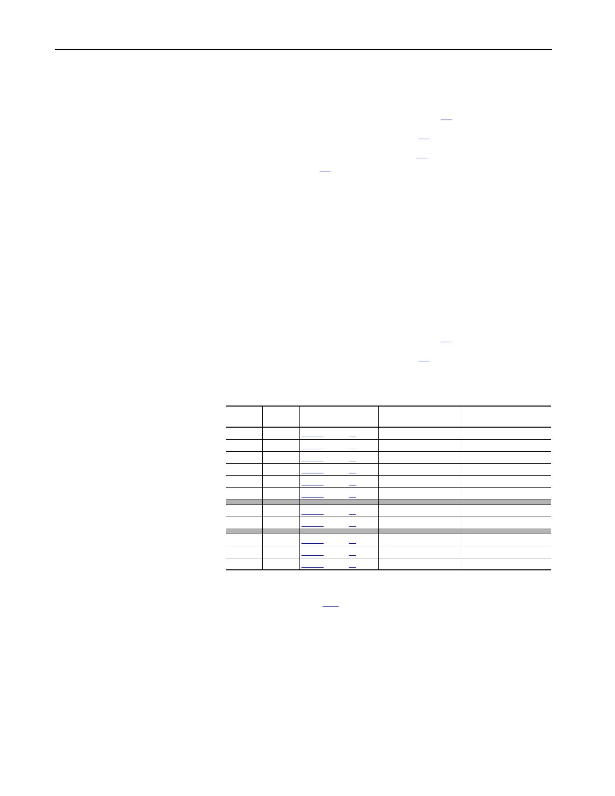
3. Measure the signal voltage at the testpoints on the control board as
indicated in the following table.
Note: For a flow chart version of the steps that follow, see Control Power
Supply Failure on page 122
.
4. If any of the signals in the table above is incorrect or missing, verify that
either 115V AC or 230V AC voltage is present at terminals U2 and V2
(control circuit power input).
• If the voltage is present and correct, continue with step 5 below.
• If the voltage is incorrect or missing, remove control power and verify
the wiring and power source to U2, V2 and correct any problems.
Test the voltage level again to verify that it is correct. If the voltage is
correct, but the drive is still inoperable, continue with step 5 below.
Name Testpoint For Testpoint Location
See…
Associated Connector-
Pin
Description
+ 5V XY5 Figure 1
on page 17 XA-1 / XA-3 / XA-5 +5V digital supply
GNDD XY6 Figure 1
on page 17 XA-2 / XA-4 / XA-6 +5V digital supply ground
GNDD XY7 Figure 2
on page 18 XA-2 / XA-4 / XA-6 +5V digital supply ground
+15V XY12 Figure 1
on page 17 XA-9 / XA-10 +15V analog supply
GNDA XY10 Figure 1
on page 17 XA-11 / XA-12 15V analog supply ground
-15 V XY11 Figure 1
on page 17 XA-13 / XA-14 -15V analog supply
+24V XY8 Figure 1 on page 17 XA-16 +24V terminal block
GNDV XY9 Figure 1
on page 17 XA-15 +24V terminal block ground
+5VEXP +5VEXP Figure 2 on page 18 XP3-1 / XP3-2 / XP3-3 +5V for DPI expansion
+12VEXP +12VEXP Figure 2
on page 18 XP3-4 / XP3-5 +12V for DPI expansion
0VEXP 0VEXP Figure 2
on page 18 XP3-7 / XP3-8 / XP3-9 DPI expansion ground

 Loading...


