Rockwell Automation Publication 20P-TG002B-EN-P - February 2018 35
Component Test Procedures Chapter 2
Check the DC Tachometer
• Verify that DIP switch S4 on the control board is set to the correct input
voltage of the DC analog tachometer. See “DIP Switch and Jumper
Settings” in the PowerFlex Digital DC Drive User Manual, publication
20P-UM001
. Also, see Figure 20 on page 110 for a circuit diagram.
• The analog tach signal is fine scaled using parameter 562 [Anlg Tach
Gain].
• See “Drive Reference and Feedback Scaling” in Appendix C of the
PowerFlex Digital DC Drive User Manual, publication 20P-UM001
,
for more information.
Check the Resolver Interface Board
The resolver feedback option module uses the resolver feedback board for
resolver connections, and the resolver interface board for external power,
status, feedback board reset, and encoder output connections.
If a “Resolver Error” (F93) fault occurs and the resolver wiring and
configuration are correct, the following light-emitting diode indicators and
testpoints on the resolver interface board can be used to verify that the board is
not damaged.
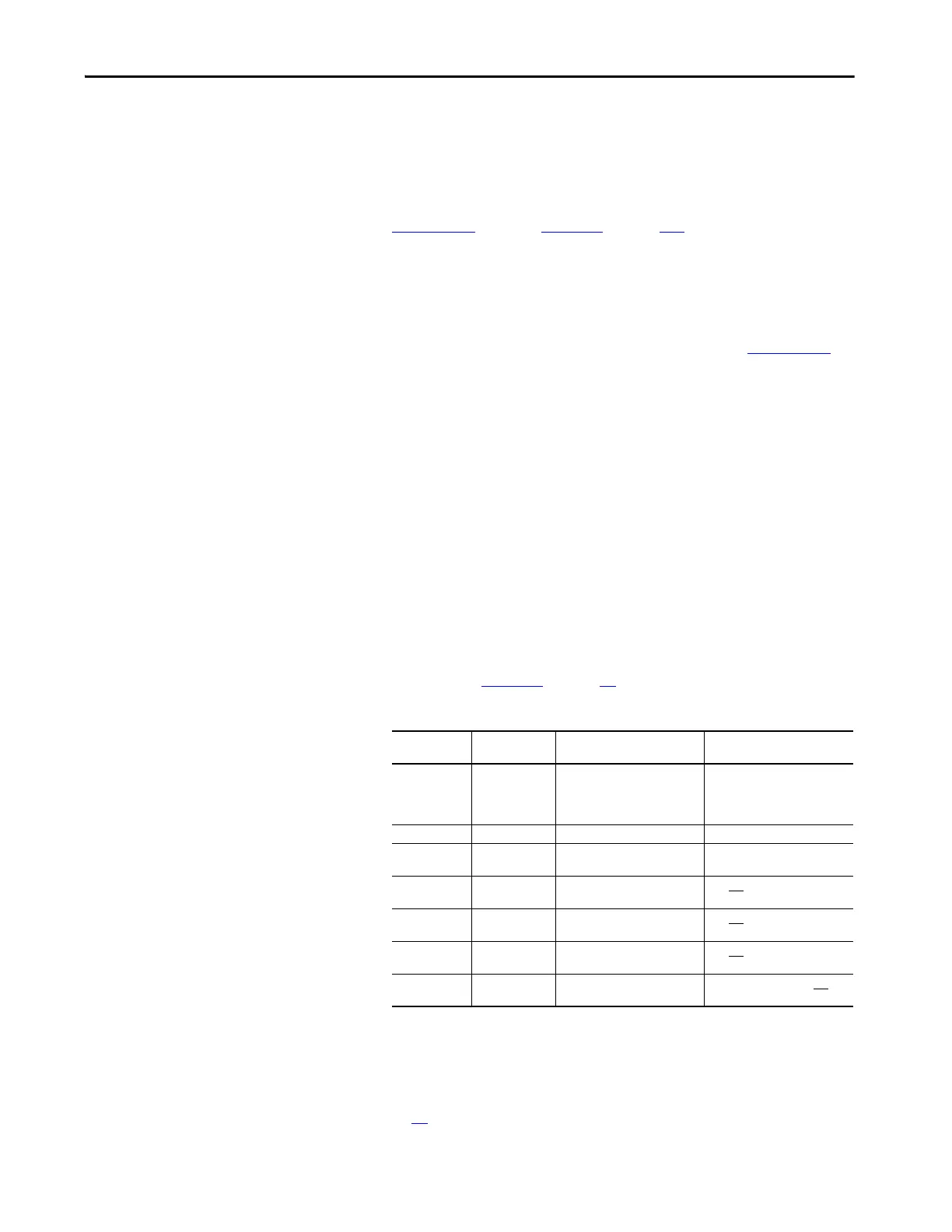
• Verify that the following light-emitting diodes are functioning as
expected. See Figure 12
on page 36 for light-emitting diodes locations
and switch settings.
If any of the light-emitting diodes that should turn on when control power is
applied fail to do so, verify that the resolver interface and resolver feedback
boards are properly seated on the appropriate connectors (XRE, P2, P3). If
problems persist, replace the resolver interface and/or resolver feedback board
(see page 48
).
Light-emitting
Diode Code
Light-emitting
Diode Color
On State Off State
D3 Red 24V overload (fuse F1 blown).
This fuse is self-resetting when it
returns to normal operating
temperature.
24V supply is OK.
D10 Green 12V supply is OK. Loss of 12V power.
D11 Green Resolver feedback board voltage
is OK.
Voltage error on resolver
feedback board.
D12 Blue Switch S1 is set to +24V for
encoder signal output on TB2.
S1 is not
set for +24V.
D16 Yellow Switch S1 is set to +12V for
encoder signal output on TB2.
S1 is not
set for +12V.
D18 Green Switch S1 is set to +5V for
encoder signal output on TB2.
S1 is not
set for +5V.
D26 Red Resolver feedback board is in
reset mode.
Resolver feedback board not
in
reset mode.

 Loading...


