76 Rockwell Automation Publication 20P-TG002B-EN-P - February 2018
Chapter 3 Part Replacement Procedures
4. Remove the pulse transformer and switching power supply boards from
the drive (see page 62
). You do not need to remove the switching power
supply board from the back of the pulse transformer board for this
procedure.
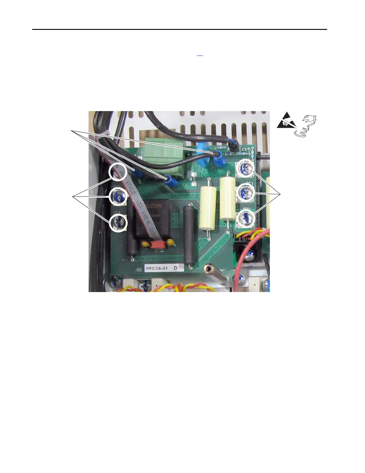
5. Remove the wires from connectors UF, UF1, VF, and VF1.
6. Remove the six screws and washers that secure the field board to the
field SCR and dual diode modules and remove the field board.
Install the Field Circuit Board
Install the field board in reverse order of removal.
• Inspect the existing X3 and XFCD cables for burn marks, cracks or
loose connectors. If necessary, replace the cables on the field board with
the new cables provided.
=

 Loading...


