Rockwell Automation Publication 20P-TG002B-EN-P - February 2018 55
Part Replacement Procedures Chapter 3
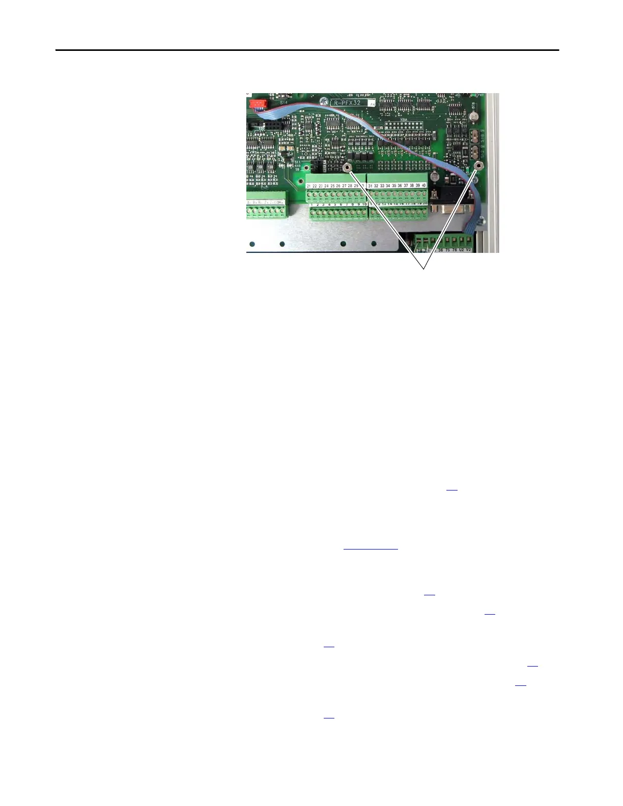
6. Remove the two stand-offs from the control board.
Install the 115V AC to 24V DC I/O Converter Circuit Board
Install the 115V AC to 24V DC I/O converter board in reverse order of
removal.
Control Circuit Board
Replacement
Remove the Control Circuit Board
Follow these steps to remove the control circuit board.
1. Read the General Safety Precautions on page 10
.
2. Save the drive and adapter parameter configuration to a HIM Set or by
down loading the drive and adapter parameters to an offline database file
using DriveExecutive™. See to the PowerFlex DC Digital Drive User
Manual, publication 20P-UM001
, for information on using the HIM or
the on-line Help provided with DriveExecutive for more information on
HIM Sets or using the HIM.
3. Remove power from the drive (see page 42
).
4. Remove the protective covers from the drive (see page 43
).
5. Remove the communication adapter and EMI shield from the control
board (see page 46
).
6. If installed, remove the resolver feedback option board (see page 48
).
7. If installed, remove the I/O expansion circuit board (see page 52
).
8. If installed, remove the 115V AC to 24V DC I/O converter circuit
board (see page 54
).
6
Tightening torque:
1.0 N•m (8.9 lb•in)

 Loading...


