124 Rockwell Automation Publication 20P-TG002B-EN-P - February 2018
Appendix C Flow Charts
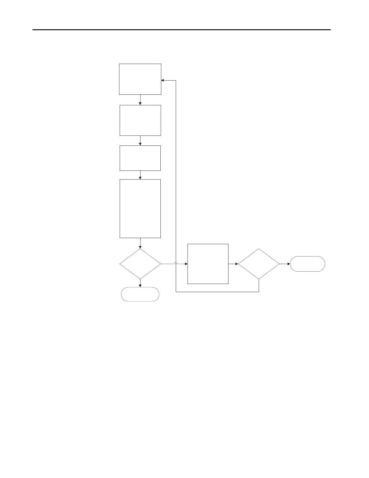
Low or Incorrect Field Current
Verify the value of
Par 351 [Field Current]
by using a DC current
clamp to measure the
DC motor eld current.
Verify that the value of
Par 280 [Nom Mtr
Fld Amps] matches the
rated eld current value
on the motor nameplate.
Is the voltage
measurement
correct?
No
Yes
Using an ohmmeter,
measure the resistance
across terminals LA-LB to
verify that the value
equals the equivalent
resistance set with
DIP switch S14.
Is the
resistance measurement
correct?
Replace the
eld board.
No
Yes
Verify that the drive rated
eld bridge current is
set correctly in Par 374
[Drv Fld Brdg Cur] and
DIP switch S14 is
congured to match.
Measure the eld current
signal at terminals LA-LB
located on the
control board. This value
should be equal to the
value of Par 374 [Drv Fld
Brdg Cur]. If these
values are equivalent,
the voltage across
terminals LA-LB should
be 1.66V DC.
Replace the
control board.

 Loading...


